I started a project to use Raspberry Zero W to control audio inputs, to turn on/off Tape2Monitor and switch Stereo to mono reproduction.
There are
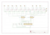
I am planning to use ten Takamisawa (Panasonic) RY5W-K relays and two ULN2003AN IC to pass control from Rasp to relays.
Software (Python) is done, all switches are working, displays are showing proper status and corresponding 3.5V from Rasp is sent to two ICs.
I have one dilemma: in order to feed 5V to specific relays (there is going to be up to 4 of them turned on at the time, one by first and up to three by second IC) can I use 5V supply from Rasp (pin 39 from schema) or should I provide additional 5V supply and connect it to pins 9 on both ICs?
Attached is a schematic and I’ll add Python script if anyone is interested.
Thanks,
Marin
There are
- Two turntable connectors (switchable by Rasp)
- Tuner
- CD/DVD
- TV/Cable
- Tape In
- Aux
I am planning to use ten Takamisawa (Panasonic) RY5W-K relays and two ULN2003AN IC to pass control from Rasp to relays.
Software (Python) is done, all switches are working, displays are showing proper status and corresponding 3.5V from Rasp is sent to two ICs.
I have one dilemma: in order to feed 5V to specific relays (there is going to be up to 4 of them turned on at the time, one by first and up to three by second IC) can I use 5V supply from Rasp (pin 39 from schema) or should I provide additional 5V supply and connect it to pins 9 on both ICs?
Attached is a schematic and I’ll add Python script if anyone is interested.
Thanks,
Marin
Attachments
Last edited:
Use an adequately rated supply, it should be able to supply Pi ands relays.
Connect your relay feed directly to the supply rather than through the Pi board if that makes sense?
I have done similar with Arduino.
Although, having looked up your relay spec, they are very low power consumption so it probably doesn't matter.
However, it is the safest way and should a faulty relay be replaced in future with a higher consumption item no harm will ensue.
THANK you Russc,
That was my thoughts as well. I have two separate LM349A-5, with 0.22mF between input and ground and 0.1mF between output and ground, one is to supply power to Rasp and the other one for relays.
That was my thoughts as well. I have two separate LM349A-5, with 0.22mF between input and ground and 0.1mF between output and ground, one is to supply power to Rasp and the other one for relays.
Why Pi zero and not an Arduino or similar? I'm not being critical, I had similar decisions to make for a project and went for Arduino because it starts immediately and runs for a long time on battery, though I started by considering Pi zero so was curious if I'd missed anything.
You can get shift-register driver chips that would only need the SPI pins to drive, rather than 10 individual GPIO pins.
You are shorting inputs together to implement mono-mode - that will not work with low impedance sources, you'll just get horrible distortion as the sources go into current limiting. You need to passively or actively mix left and right to get mono, perhaps like this:

Can you explain the RIAA_IN1 and RIAA_OUT1 in detail, they seem rather odd.
You are shorting inputs together to implement mono-mode - that will not work with low impedance sources, you'll just get horrible distortion as the sources go into current limiting. You need to passively or actively mix left and right to get mono, perhaps like this:
Can you explain the RIAA_IN1 and RIAA_OUT1 in detail, they seem rather odd.
Why Pi zero and not an Arduino or similar? I'm not being critical, I had similar decisions to make for a project and went for Arduino because it starts immediately and runs for a long time on battery, though I started by considering Pi zero so was curious if I'd missed anything.
It is just because I am familiar with Rasp, but not with Arduino B)
You can get shift-register driver chips that would only need the SPI pins to drive, rather than 10 individual GPIO pins.
You are shorting inputs together to implement mono-mode - that will not work with low impedance sources, you'll just get horrible distortion as the sources go into current limiting. You need to passively or actively mix left and right to get mono, perhaps like this:
Can you explain the RIAA_IN1 and RIAA_OUT1 in detail, they seem rather odd.
THANKS Mark for VERY valuable input, regarding mono mode, I will adjust my schema to address it properly.
These two RIAA connectors are for phono pre (out goes as input to RIAA, in is out of RIAA pre), which is on a separate board.
It is just because I am familiar with Rasp, but not with Arduino B)
Well, you can also use the Pi as a music server.
I was surprized how cheap the Pi Zero is.
These two RIAA connectors are for phono pre (out goes as input to RIAA, in is out of RIAA pre), which is on a separate board.
You have 2 turntables?
Otherwise I'd have connected the turntable direct to the phono preamp & connected the output of that to a line level input.
Avoids switching very low level signals.
You could always use 2 phono pre-amps.
Well, you can also use the Pi as a music server.
I was surprized how cheap the Pi Zero is.
That, with Rasp 4, 8G RAM and, either BOSS or HiFiBerry, is a next project B)
You have 2 turntables?
Otherwise I'd have connected the turntable direct to the phono preamp & connected the output of that to a line level input.
Avoids switching very low level signals.
You could always use 2 phono pre-amps.
I don't yet, but that is in line with my planned sources. If I am lucky enough to make my (friend) machinist to finish a turntable (that one is dragging for years, just because we are friends and we spend more time doing other things than working in his workshop) I will have two tone arms, one with stereo and another one with mono cartridge.
I might eliminate Stereo/Mono relay and directly connect the mono source to phono pre.
It's been a long time, and lots of thinking, planning, changing design, I came with the following:
This is a RIAA pre-amp part:

This one is an input selector, controlled with Raspberry, with connectors for switch and display:

Here is the entire board, top side first:

...and bottom side

THANK YOU IN ADVANCE!!!!
Marin
- Make an input selector and phono pre-amp on a single board (as s,mall as possible, because of audio rack space constraint)
- Place entire power supply parts on the same board
This is a RIAA pre-amp part:
This one is an input selector, controlled with Raspberry, with connectors for switch and display:
Here is the entire board, top side first:
...and bottom side
THANK YOU IN ADVANCE!!!!
Marin
I would not try to power the relays directly from a Raspberry or Ardunio, the relay current is kind of close to limit of the micro to supply. Instead I like to connect the relay power through a small transistor and use the Raspberry or Ardunio to turn on the transistor. I have already done the input selector for a preamp with balanced or single ended inputs. See my thread under my name and preamp volume, for same schematics and layouts to help with your project. The long thread has three designs, ignore the first two and do to need the end of the thread for the final volume control version and the input selection schematic, PCB, and Code. Good luck with your project.
I think they are being buffered by the ULN2003A chips, a darlington chip array. I'd also suggest for those using arduino to look at the new pico and picow. I believe less expensive at the board than arduino now. I've started using them. RP2040W (picow) without headers is 6 ea on a board.
I bought 10 Arduino Nanos for $30, hard to beat $3 each. Don't know how they can make them for that amount.
You are correct Mike, there is a ULN2003A between Rasp and relays. I am using Rasp Zero.I think they are being buffered by the ULN2003A chips, a darlington chip array. I'd also suggest for those using arduino to look at the new pico and picow. I believe less expensive at the board than arduino now. I've started using them. RP2040W (picow) without headers is 6 ea on a board.
Did they come with wifi? I did not see inexpensive nano's with wifi, only non-wifi. The picow has wifi on the board. W/o wifi I think they are 4, so slightly more than the nano. And yes, I've no idea how they do it at these price points. A power tran is often more.I bought 10 Arduino Nanos for $30, hard to beat $3 each. Don't know how they can make them for that amount.
Low price point comes from using parts designed for the low-end smart-phone market (which sell in millions quantity and thus are cheap) and having fully automated assembly and testing. Basically mass-production.
- Home
- Source & Line
- Analog Line Level
- Raspberry based input selector