
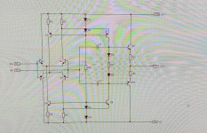
Schematic principle
It's a full simmetric bipolar opamp.
Open loop Gain: 80dB
Open loop BW: 10KHz
GBW: 80MHz
The current consumption can be adapted, depending on the final application, as well as the current bias in the output stage.
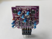
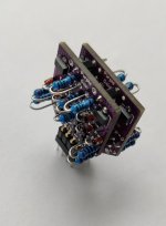
One single pcb 25x25mm can be used to make a dual opamp.
This way you will get 16 pcbs in a board 10x10cm, for a total of 80 pcbs, from JLPCB for 2$!
I tried it in the output stage of a DAC and it sounds great.
It's a full simmetric bipolar opamp.
Open loop Gain: 80dB
Open loop BW: 10KHz
GBW: 80MHz
The current consumption can be adapted, depending on the final application, as well as the current bias in the output stage.
One single pcb 25x25mm can be used to make a dual opamp.
This way you will get 16 pcbs in a board 10x10cm, for a total of 80 pcbs, from JLPCB for 2$!
I tried it in the output stage of a DAC and it sounds great.
Attachments
Less overhang from the PCBs. As something that gets retrofitted it'll have fewer compatibility issues if narrower.
Well, SMD diodes and resistors can also be mounted in this PCB. As first prototype I wanted to do it in this way.
So, as BJT I used:
Q1,Q2,Q6,Q8=BC846B
Q3,Q4,Q5,Q7=BC856B
Q9=BCX56
Q10=BCX53
D1=D2=D3=D4=D5=D6=1N4148
C1=C2=47pF
The circuit is quite flexible and can be designed looking at the application.
Values used by me with Vcc=+/-12V:
R1=R2=R3=R4=220 ohm
they fix the current of the differential pairs and of the folded cascode stages.
If you decrease the current, you have an higher input impedance and a lower gain.
R5=24Kohm. It can be lower, depending on the supply voltage.
R7=R8=15 ohm
R6=330 ohm: with it the pushpull output stage is biased at 12mA.
Best is that you do some simulations and make your choices.
In my case I ended up to around 20mA of current consumption, that is much more compared to a standard opamp: so please be sure that your circuit is capable of delivering such a current.
Thanks to those values the output stage can deliver and interesting amount of current without switching to class B, it depends on what is the load in your application.
Reducing R6 you will decrease the output bias.
Another interesting aspect of this circuit and pcb is the fact that it can be easily modified to try (and to listen to) other solutions:
- Q5 and Q6 can be removed, using only R2 and R4 as less-ideal current generators for the input differential pairs. If your supply is good and silent, you could get benefits from this mod, from sonic point of view (of course the PSRR will be worse: can we accept that?)
- the circuit can be modified to the single ended version, removing Q3, Q4, Q5 and R2 and putting R3=2*R1. The open loop gain will be a bit less, the input impedance a bit higher.
What I appreciate in all these circuits is the absence of current mirrors, as I do believe they tend to compress the dynamic of the signal.
Very cool. Nice job.
There is another reason to consider an all SMD configuration besides size, and that is current supply chain issues, there may be a better supply and more options with SMD components.
I've found the 0805 a sweet spot in my discrete op-amp designs. I use thin film resistors...
For small signal diodes I use SOT-23 or SOD-123 packages, and BJT in SOT-23 and SOT-223 packages.
I don't sell pcbs, as I am not interested in doing business with my hobby.
You have all the info, you can make your own pcb if you like, it is a nice exercise.
What I do recommend to everybody is to debug the opamp once finished: use a good oscilloscope and check if you have self oscillating problems at the otuput.
The circuit is unity gain stable, but it's always better that you check what you did.
As it depends on which values and components you will use, in case of oscillation you could increase the value of the two caps.
Thanks.
Can you give some info or link of your discrete opamps?
I'd be delighted, I haven't posted the design here but would be happy to share with you. Send me a PM.. 🙂
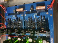
I have been looking for a leach type gain stage for my modular preamp. As you can see the module would have an area ample enough for 16 transistors or more. (current mirrored diamond buffer in the pic) i havent been able to find a leach type opamp in that level of complexity tho.
When the circuit is too simple you can hear the psu throuth its compromised psrr and i dont want to live with that
And since im not a circuit designer the search continues...
When the circuit is too simple you can hear the psu throuth its compromised psrr and i dont want to live with that
And since im not a circuit designer the search continues...
Attachments
I will start a new thread out of respect for the OP. 🙂
(Edit) Here: https://www.diyaudio.com/forums/ana...aying-discrete-op-amp-design.html#post6848092
(Edit) Here: https://www.diyaudio.com/forums/ana...aying-discrete-op-amp-design.html#post6848092
What values of R2 and R4 should be used to adapt this discrete opamp for supply voltage of +-6.80 volts, with and without Q5 and Q6? This is about the voltage I see for the output opamp in my Topping D50s DAC, which is supplied with 5VDC externally? Thanks.
- Home
- Source & Line
- Analog Line Level
- Purple Gain:a discrete opamp