I have a left over analog board suited for the TDAI-2170 and TDAI-3400 with a nice AK5294A ADC on it. I didn't find a service manual online but it seems fairly easy to run it stand alone: I managed to select the inputs and the +6dB gain by writing from an MCU to the 74HC595 which is accessible through the multi pin connector.
The board expects 3 power supplies of (I believe) +12, -12 and +5 volts, but there is one thing I don't understand:
The relays have 12V printed on them and are directly supplied from the input voltage, so I don't think I should feed higher than 12V to the board. But there are two regulators in series on the board: a 78M09G and a 78M05G, generating the 5V needed for the AK5394A. But the 78M09G has 10.4V at it's input and 8.7V at it's output and the data sheet says drop out is 2V (the 8.7V go into the 78M05G which outputs 5V). What do you think?
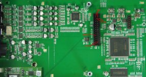
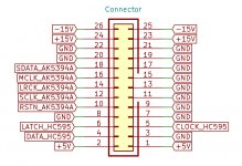
Please could anybody who has a Lyngdorf measure the voltages on the pins shown in attached picture for me? That would be of great help! (The attached picture shows the motherboard inside the Lyngdorf with the multi pin connector where the ADC module connects to.)
The board expects 3 power supplies of (I believe) +12, -12 and +5 volts, but there is one thing I don't understand:
The relays have 12V printed on them and are directly supplied from the input voltage, so I don't think I should feed higher than 12V to the board. But there are two regulators in series on the board: a 78M09G and a 78M05G, generating the 5V needed for the AK5394A. But the 78M09G has 10.4V at it's input and 8.7V at it's output and the data sheet says drop out is 2V (the 8.7V go into the 78M05G which outputs 5V). What do you think?
Please could anybody who has a Lyngdorf measure the voltages on the pins shown in attached picture for me? That would be of great help! (The attached picture shows the motherboard inside the Lyngdorf with the multi pin connector where the ADC module connects to.)
Attachments
Last edited:

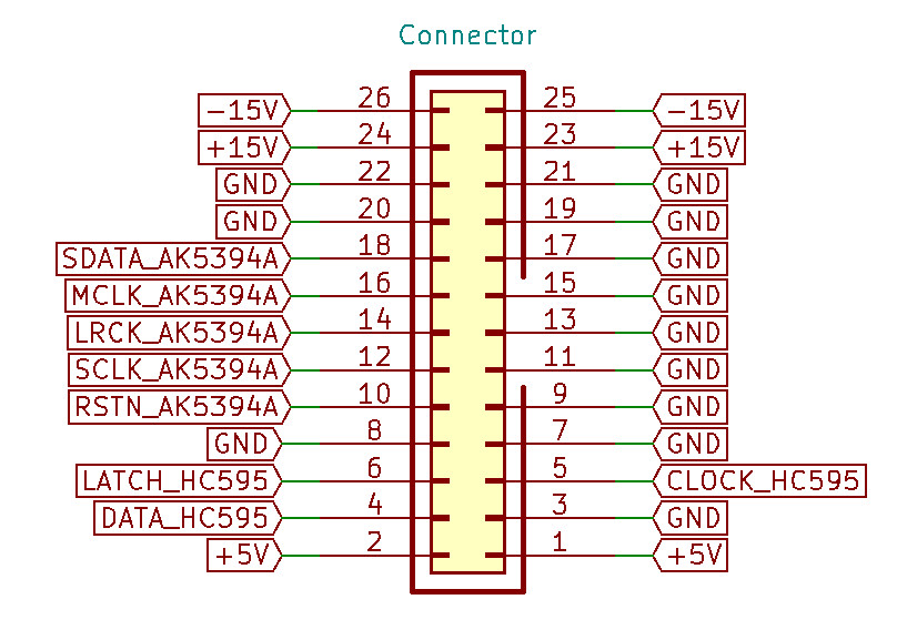
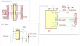
Yes, I simply overlooked that the relays sit between the source and the collectors of the transistors. Here a diagram of the connector shown in the TO:
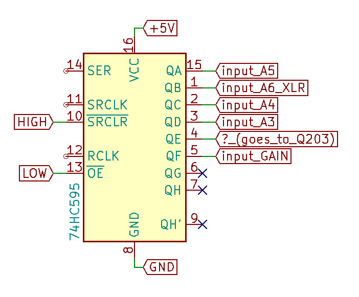
The diagram of the input selector (A3-A6 are the inputs, QF adds +6dB of gain, QE goes to a transistor labelled Q203 but I don't know yet what it does):
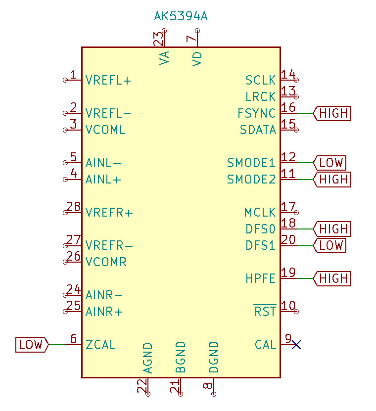
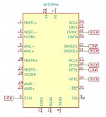
This is how the ADC is configured:
The diagram of the input selector (A3-A6 are the inputs, QF adds +6dB of gain, QE goes to a transistor labelled Q203 but I don't know yet what it does):
This is how the ADC is configured:
Attachments
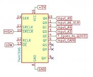
Following the tracks from Q203 there seems to be nothing really operated by QE, just a couple of diodes in series dropping the output voltage of Q203 step by step. It seems that Q203 is only there to keep the current draw constant during relay switching: I noticed that switching the +6dB gain relay causes exactly the same amount of current draw as Q203, but maybe this is a silly idea...?
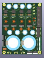
Some progress: I designed and built a power supply and MCU board for the ADC, see attached rendering. The MCU is an ATtiny and operates the input selector, the reset line, LEDs etc. The backside of the PCB carries a 74AUP1G74 based circuit which can take in MCLK and generates an output frequency with half the frequency of the input...
Attachments
Last edited:
 Thanks! I have a semi populated AK5394 PCB and
 I used the smaller diyinhk xmos, it worked, but only with the flip flop circuit for MCLK. Please keep us updated about your ADC project!
 the ADC bring-up to be easy. I still wait some of the components.
- Home
- Source & Line
- Analog Line Level
- Lyngdorf module voltages