My experience with the 2134 is that it doesn't like being used as a unity gain buffer. It is perfectly happy as a unity gain inverter (like in tone control circuits). I also used it in a non-inverting gain stage with a voltage gain of 1.4 with no problems.
I have successfully configured it as a unity gain buffer with a few extra parts (couple of resistors and ceramic capacitors).
I built a prototype of this circuit Project 99 - Subsonic Filter with op amp sockets. I tested three op amps in the circuit: NE5532, LM4562, and OPA2134.
NE5532 worked great but DC offset was 45 mV.
LM4562 worked great and DC offset was 3 mV 😎
OPA2134 oscillated. I tried using one 2134 and one 4562 and it oscillated.
To me, the 4562 should be the touchiest, with its 50 mHz GBP. But it seems that's not the case.
I have configured the 5532 as a follower with 0.1 to 0.2 mV DC offset, but obviously this isn't doable in a whole lot of circuits.
So has anyone else had a similar experience? I'm always looking for new tricks. 😉
It is not a buffer but a Sallen-Key filter. It could present the OPA an impedance it doesn't like. I would put it in LTSpice and see if it oscillates there as well. If it is stable in LTSpice you are doing something wrong in the peripheral space, like power supply decoupling. Especially if your oscillation is in the MHz range.
Yes. The op amp is configured as a unity gain buffer, but with feedforward feedback through the 47K resistors.
I solder ceramic decoupling caps directly to the chip pins on the bottom of the board. I always do this. Plus every chip has a local 10 uF bypass, and the board has a 47 uF bypass. Again, I always do this.
I have had issues with the 2134 in non inverting configuration before. I was not surprised at this result.
Like you said, I might be doing something wrong. But no problem; I will build the circuit with the 4562. I recently ordered a couple for evaluation and will be ordering a batch.
I haven't done LT Spice ever. I learned the old fashioned way to slog it out with KVL and KCL with a (gasp) pencil and paper. I know, I'm a dinosaur.
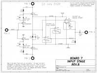
It works great in the First Watt M2x power amplifier, deployed as a unity gain buffer. No oscillation observed among a dozen different implementations, by diyAudio members on three different continents. Schematic below.
The PCB contains two DIP-8 sockets, one for a "single" opamp and another for a "dual" opamp. DIY builders can plug in either an OPA134 into the "single" socket, or an OPA2134 into the "dual" socket. Whichever they like, whichever they have in their parts bin. Just don't populate both sockets at the same time!
_
Attachments
I hope to figure out what I'm doing wrong.
I have tone control boards (bass and treble controls) that use the 2134 and they're excellent. The First Watt schematic referenced does not use any of the "tricks" I used to make the 2134 work as a unity gain buffer.
I will move forward with the 4562. I popped it into various circuits and it worked in all of them without a hitch. I'll use the 2134 where it's worked best for me before.
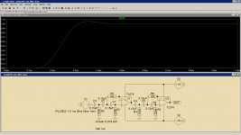
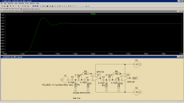
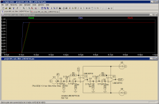
Oh, but you should. This tool gives so much insight! Like what changing the opamps does to this circuit. I just tested the pulse response for TL072 (here TL074) and OPA134 (single OPA2134). The OPA is much faster and here has a significant overshoot. Temperamental chippie that... 😀I haven't done LT Spice ever
The sim files are in the ZIP file.
Attachments
Well thank you. That is very insightful.
As I thought. And SPICE agrees with me.
How about simulating it with the 4562? Thanks.
Temperamental chippie that...
As I thought. And SPICE agrees with me.
How about simulating it with the 4562? Thanks.
I use ltspice quite a lot and its been very productive.
But it does have its limitations and is only as good as models input into it.
I designed a valve/mosfet headphone amp.
It simulated fine.
So got a pcb made and fired it up and nothing.
I had to add a grid pull up resistor of 470k to B+ before it would pass any current.
I dont let one bad experience put me off as mostly ltspice works great.
I am using the 2134 as unity gain non-inverting and have not seen any stability problems with it. The bean drives an easy resistive load.
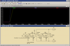
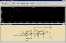
That was an interesting challenge. According to this post the model for LM4562 is broken in LTSpice. There is another model, for the LME49710 that does work as well as a fixed model for the LM4562. Both give the same results. I don't trust them as the OPA gives totally different results. Or maybe the LM(E) chips are just much faster still than the OPA. Whichever the case, there is no overshoot so that is good.How about simulating it with the 4562? Thanks.
Attachments
Wow! That's very interesting.
I first tested the 4562 just a few days ago. Based on its specs I expected it to be crankier than I'm used to. But I've gotten it to work just fine in a few of my circuits. I stuck a few in my preamp and couldn't hear a difference. I think that's a good sign.
I've been looking for a replacement for the 5532. It seems like everything works with the 5532, but the input bias current can be a real issue in some circuits (like circuits that have a potentiometer). The 2134 is great for a lot of circuits but not exactly a plug in replacement for the 5532. TL072 audibly degrades my circuits. Maybe the 4562 is my way forward.
Is the popcorn noise issue with LM4562 solved? I have experienced it a few times and therefor stopped using them.
They don't do it all but when they do they keep doing it. If used an IC socket is mandatory I think so it is easy to replace them. Its brother LME49860 does not have it AFAIK and I used these a lot (higher power supply voltages possible as well). I never could get my hands on LME49990 which is a JFET input type that is supposed to perform good.
Today I would consider OPA1656, a very good SMD CMOS opamp.
Today I would consider OPA1656, a very good SMD CMOS opamp.
Last edited:
I was not aware of issues with the 4562. I decided to try it after reading so much about it and looking at the datasheet.
I'm trying to avoid surface mount chips. I built one project using LME chips, made a board with old fashioned stencils and everything. It still works great in daily use for several years but using surface mount devices is going to really slow me down, and I'm pretty slow already.
I'm trying to avoid surface mount chips. I built one project using LME chips, made a board with old fashioned stencils and everything. It still works great in daily use for several years but using surface mount devices is going to really slow me down, and I'm pretty slow already.
That's a pity as OPA1656 is the first CMOS opamp that shines in audio (and it's not hard to solder). Its cousin OPA2156 also is OK but read data sheets for details. OPA2156 has rail to rail input voltages possible but at a cost.
Last edited:
I agree; the OPA1656 is arguably the best audio opamp around these days. I have a bunch mounted on DIP adapters.
Jan
Jan
I had a fun time laying out my own SMD-to-DIP adapter boards with four SMD bypass capacitors on the bottom side of the board. There's no GND on the board of course, so one must be flexible, but overall I was quite pleased with the results. And if you fab them at a PCB shop whose price is X Euros per square cm of PCB area, such as OSH Park in the US, total price is delightfully low.
Yes, I got boards from them last week and they are both cheap and beautiful. Especially the "after dark" version they are offering (the purple ones require special taste 🙂). I just wish I hadn't made the mistake of using 0402 parts.
OSH Park Docs ~ Services ~ After Dark
What is wrong with a GND wire for decoupling on a SMD-to-DIP adapter? I must admit that I prefer to have boards layed out for SMD instead of using adapters.
OSH Park Docs ~ Services ~ After Dark
What is wrong with a GND wire for decoupling on a SMD-to-DIP adapter? I must admit that I prefer to have boards layed out for SMD instead of using adapters.
Last edited:
- Home
- Source & Line
- Analog Line Level
- OPA2134 Stability