I found these Vishay NOMCA 8 indépendant same value R
TC absolute +- 25 ppm
TC tracking +- 5 ppm typical
The come in 1K,2K,5K,10K,20K,50K
With four of these, I could implement
Output stage
Gain +8 OPA non inverting with R,7R
Gain -1 OPA inverting with 4R,4R
Input stage
Gain 0,2 OPA with 5R,5 and 5R,R
Thanks to TC tracking 5 ppm, with 4 that can all drift the same way, I should get 20 ppm
0.001dB is 115ppm.
I see I must keep
temperatures + - 6°C ( 115/20 ).
Here there might be a chance for very low drift.
I do not get the point.AC response over audio frequencies is going to be a limit - check how many decades of margin is needed between amp corner frequencies and audio band limits for 100 ppm error
DC coupling would work for the lower corner but the upper limit is tough, gain intercept even 2 decades beyond 20 kHz and 100 dB excess gain @20k...
Sure the gain is not the same over the band because of the high frequency roll off and low frequency roll off.
Say, there is some gain drift at 1 KHz, don't we have the same drift at 10KHz and 100Hz ?
I imagine the drift is a translation up or down of the Amplitude versus Frequency plot.
I must be missing a point.
Even if you should want very good gain flatness, Pythagoras may come to the rescue.
Suppose the op-amp has infinite DC loop gain and a first-order roll-off from 0 Hz all the way to infinity Hz, that its gain-bandwidth product is GBP and that the closed-loop response has to be flat within +0 ppm/-100 ppm up to 20 kHz while the closed-loop gain is about 8.
The response of the closed-loop amplifier will then have a first-order roll-off with a corner frequency of GBP/8. The magnitude of the response will be
8/sqrt(1 + (8 f/GBP)^2)
so normalized to the DC gain, that's
1/sqrt(1 + (8 f/GBP)^2)
Equating this to 0.9999 (100 ppm roll-off):
(8 f/GBP)^2 = (1/0.9999)^2 - 1
GBP/f = 1/sqrt(((1/0.9999)^2 - 1)/64) ~= 565.642998
Hence, for 20 kHz and a closed-loop gain of 8, a gain-bandwidth product of just over 11.3 MHz suffices to get the response flat to +0 / -100 ppm.
About my reference to Pythagoras: the input signal of the op-amp is the sum of the error signal and the feedback signal. The error signal of my hypothetical op-amp is 90 degrees out of phase with the feedback signal, so Pythagoras' theorem relates the magnitudes of the input signal, feedback signal and error signal.
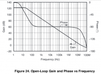
I'm pretty sure that non-dominant poles or other singularities with corner frequencies far in the megahertz range (say > 3 MHz) won't change the conclusion much, as their roll-off or roll-up at 20 kHz will be negligible. I'm not so sure about pole-zero pairs at lower frequencies, like the wobble around 200 kHz in the NE5534 loop gain versus frequency plot in the Philips/NXP datasheet.
Suppose the op-amp has infinite DC loop gain and a first-order roll-off from 0 Hz all the way to infinity Hz, that its gain-bandwidth product is GBP and that the closed-loop response has to be flat within +0 ppm/-100 ppm up to 20 kHz while the closed-loop gain is about 8.
The response of the closed-loop amplifier will then have a first-order roll-off with a corner frequency of GBP/8. The magnitude of the response will be
8/sqrt(1 + (8 f/GBP)^2)
so normalized to the DC gain, that's
1/sqrt(1 + (8 f/GBP)^2)
Equating this to 0.9999 (100 ppm roll-off):
(8 f/GBP)^2 = (1/0.9999)^2 - 1
GBP/f = 1/sqrt(((1/0.9999)^2 - 1)/64) ~= 565.642998
Hence, for 20 kHz and a closed-loop gain of 8, a gain-bandwidth product of just over 11.3 MHz suffices to get the response flat to +0 / -100 ppm.
About my reference to Pythagoras: the input signal of the op-amp is the sum of the error signal and the feedback signal. The error signal of my hypothetical op-amp is 90 degrees out of phase with the feedback signal, so Pythagoras' theorem relates the magnitudes of the input signal, feedback signal and error signal.
I'm pretty sure that non-dominant poles or other singularities with corner frequencies far in the megahertz range (say > 3 MHz) won't change the conclusion much, as their roll-off or roll-up at 20 kHz will be negligible. I'm not so sure about pole-zero pairs at lower frequencies, like the wobble around 200 kHz in the NE5534 loop gain versus frequency plot in the Philips/NXP datasheet.
Last edited:
yes Pythagoras helps a lot - but if you calc a need for >10 MHz GBW then I'd buy something with >20 MHz "typical" spec
OPA827 would be a candidate by my thinking
If the source Z is low enough to warrant then the OPA211 but feedback layout may be tough
even have to watch the op amp's open loop gain low freq response - need lots of excess gain where it flattens out
OPA827 would be a candidate by my thinking
If the source Z is low enough to warrant then the OPA211 but feedback layout may be tough
even have to watch the op amp's open loop gain low freq response - need lots of excess gain where it flattens out
Gain flatness is an issue independent of gain drift, I think.
For well behave amplifiers, the not so flat gain is a progressive gain droop
A gain drift at a center frequency, can only be smaller at high or low frequencies.
All it takes for this to be true, is a monotonic droop, in other word no peaking.
For well behave amplifiers, the not so flat gain is a progressive gain droop
A gain drift at a center frequency, can only be smaller at high or low frequencies.
All it takes for this to be true, is a monotonic droop, in other word no peaking.
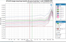
Sorry I thought the legend said it all. It is the AP in loop-back, essentially measuring its own oscillator. I was working on a very low gain drift circuit as well, and it showed some drift with temperature. In the first hour, each curve is at 10 minutes interval, later the intervals are longer, see the legend in the right column.
So then I tested the AP itself, with the test you see in #41, and found that the AP drifted more than my circuit. Note that you cannot conclude from this whether it is the oscillator that drifts or the analyzer.
So if you can do better than this, you are in good company ;-)
Jan
So then I tested the AP itself, with the test you see in #41, and found that the AP drifted more than my circuit. Note that you cannot conclude from this whether it is the oscillator that drifts or the analyzer.
So if you can do better than this, you are in good company ;-)
Jan
I am not familiar with the AP.
I had guessed the display was showing a drift, but could not figure, drift of what.
I understand you are working on very low drift circuits, at the limit of the AP own drift.
Do you think my aim at 0.001 dB stability is insane ?
I know it is likely.
With the resistor array Vishsay NOMCA with TC tracking 5 ppm, it seems possible. Asking for a 6℃ range, for ambient and self heating.
The specs doesn't Rth.
Gain flatness is an issue independent of gain drift, I think.
For well behave amplifiers, the not so flat gain is a progressive gain droop
A gain drift at a center frequency, can only be smaller at high or low frequencies.
All it takes for this to be true, is a monotonic droop, in other word no peaking.
Either I don't understand you or I disagree with you. The way I see it, the gain-bandwidth product of the op-amp is bound to be temperature dependent to some extent, so at high frequencies you get the normal gain drift plus something extra from the varying gain-bandwidth product.
I am not familiar with the AP.
I had guessed the display was showing a drift, but could not figure, drift of what.
I understand you are working on very low drift circuits, at the limit of the AP own drift.
Do you think my aim at 0.001 dB stability is insane ?
I know it is likely.
With the resistor array Vishsay NOMCA with TC tracking 5 ppm, it seems possible. Asking for a 6℃ range, for ambient and self heating.
The specs doesn't Rth.
0.001dB is a factor of about 0.012%. If you allow 6 degrees temp change, that means that the gain can have maximum 0.002%/degree temperature drift.
I don't think you can do that without an oven. With an oven, it's a no-brainer. It is not hard to build a small enclosure with a control circuit that keeps the temperature constant at 0.01 degrees or better.
Jan
I overlooked that the gain-bandwidth product is temperature dependent.The way I see it, the gain-bandwidth product of the op-amp is bound to be temperature dependent to some extent
Now, I understand this is an issue about gain drift.
Which posts point to this ?
I derived my 6℃ from Marcel reasoning in post 23.0.001dB is a factor of about 0.012%. If you allow 6 degrees temp change, that means that the gain can have maximum 0.002%/degree temperature drift.
I don't think you can do that without an oven. With an oven, it's a no-brainer. It is not hard to build a small enclosure with a control circuit that keeps the temperature constant at 0.01 degrees or better.
Jan
0.001 dB is 115ppm
Arrays are TC tracking 5ppm
I have 4 arrays setting gains with op amps, so 20ppm
115/20 gives about 6℃.
Is there a bug ?
A am glad to know an oven is no brainer, and I could not imagine, that accurate.
Last edited:
It is not hard to build a small enclosure with a control circuit that keeps the temperature constant at 0.01 degrees or better.
Jan
Just a warning: it is very easy to unintendedly make a thermal circuit that creates a pole-zero pair in the control loop that slows down the accurate settling of the temperature. For example, when you have an inner enclosure, thermal isolation, larger enclosure with a substantial heat capacity and another layer of thermal isolation.
I overlooked that the gain-bandwidth product is temperature dependent.
Now, I understand this is an issue about gain drift.
Which posts point to this ?
I think no-one mentioned it explicitly until post 54.
The LM358 brags on page 1 of its datasheet, that its gain bandwidth product is temperature compensated and thus, constant across temperature. This was when assistant professors eager to make tenure, were publishing papers in the partially reputable journal "Electronic Letters", with titles like: "Grounded capacitor bandpass filter using the amplifier pole" (citation)
- Status
- This old topic is closed. If you want to reopen this topic, contact a moderator using the "Report Post" button.
- Home
- Source & Line
- Analog Line Level
- Ultra low drift GAIN