I'm going through a phase in my life when I want to design 3-way conventional box speakers with large (10" or 12") woofers and large midranges, where the midrange will almost have LF extension to act as the midbass in 2-way designs. Having loved the Darbari which I had since 2014, I now want to see if I can make them smaller, perhaps with less expensive crossovers, and better.
So, on this journey, I realise I am hesitant to design a passive crossover at, say 100Hz to 250Hz, which is where my crossover between midrange and woofer will happen. I am afraid the coils and crossovers will be large, and even hard-core fans of passive crossovers seem to be happier doing this one part active, and driving the woofer with a separate amp channel. I'm thinking of doing (at least) the same, so I need a 2-way active crossover.
I want to use something which I can embed inside the speaker, throw in the mains PSU and two amp channels, and basically make the speaker a standalone, powered active speaker. I'll be happy to do a passive xo between mid and tweeter. I've worked with difficult passive crossovers for the Asawari 4 and Asawari 5, so I feel more confident now that I'll be able to do a decent job there even with fairly difficult drivers. What I need active for is just the low-frequency split between mid+tweeter on one side and woofer on the other.
I've worked with MiniDSP hardware (the Darbari runs on the 4x10HD), but I balked at the idea of using a 2-in 4-out box (their smallest) for my simpler 1-in 2-out requirement. I am hoping that any active analog crossover I design will be as clean but less expensive than their 2x4HD. The 2x4HD would have made me invest USD 200 per speaker enclosure -- I'm hoping my module will be much less expensive. Also, KiCAD has become really powerful, so I thought I'll just wing it. Make my own. Fabbing a prototype PCB is also super-easy these days -- I use PCBPower with super results.
Studies
Most of my learning is from Don Lancaster's Active Filter Cookbook and Doug Self's Design Of Active Crossovers. Linkwitz' website. Rod's ESP pages. Randy Slone's Audiophile Projects Sourcebook. Plus years of trickle-down learning from everyone. I missed Bob Ellis' active xo project and group buy which happened 15 years ago, so I didn't learn much from there. I found the PDF of their builder manual online recently, but it wasn't very clear without a PCB on hand. Doug Self's book is the most useful.
No allpass filters
In my studies, the biggest difficulty I have faced is in understanding the use of allpass filters. When Linkwitz says "there's no point in designing an accurate crossover unless you also correct the delay", you tend to sit up and dig deeper to figure out just what problem he's fixing. This is one piece which doesn't show up in passive xo designs, so I never learned about them in my previous speaker designs, all passive. So I studied all I could find, took my final set of confusions to this thread, processed the helpful answers, and concluded that if I design active xo the way I have been designing passive xo, I don't need allpass filters. So, my circuit will not have provision for any.
Powering from power amp rails
I'll design the board to take AC from the secondaries of the transformer. I'll have one toroid per speaker enclosure, and this will have high(er) voltage secondaries, because they'll power the power amp channels. I'll avoid asking for a separate pair of windings just for my xo -- I'll do a voltage dropper after the bridge, on my board, and feed its output to the voltage regulator ICs. A voltage dropper is just a TO220 transistor, a zener, some R and C per rail. Rod Elliot's pre-regulator supplies the basic idea.
SMD 4-opamp chips
I took a deep breath and decided to bite the bullet and go with 4-opamp chips. My simple 2-way already requires 9 opamps it seems. Placing 5 dual-opamp chips seems just too messy in this day and age. Since many of the best chips in this category are only available in SOIC-14 and TSSOP packages, I'll provide for those SMD footprints on the PCB, and will also provide for 14-pin DIP pads so that people can do opamp rolling using SOIC-14 to DIP adapters. I personally do not have appetite for opamp rolling. If no one tells me otherwise, I'll go with OPA1604 4-opamp chips. If my opamp count remains at the current 9, I'll use two 4-opamp chips and one dual-opamp LM4562 DIP-8 chip.
SMD capacitors?
I'm not comfortable soldering SMD parts, but I think I'll use SMD for the filter capacitors, because the through-hole high quality box capacitors can be as large as 13mm x 6 mm, which is really too big when I'm going to use so many of them. So I'm thinking of using 1206 SMD footprints, the biggest there is in SMD.
Many capactors, all resistors and other components will be through hole.
The filter blocks themselves
People who build textbook electrical active filters have life easy -- they never have to learn about equal-component-value versus unity-gain S&K filters, or about the fact that they may be forced to manage the gain from stage to stage, because sometimes you may need to just accept whatever gain the topology gives you, once you fix your Q. So I'll try to make suitable provisions for these things in my schematic.
For the LPF blocks, the first component in the signal path is a resistor. This is useful because one can split this resistor into two and make a voltage divider, and achieve some gain reduction, all the while conforming to the filter formula. (This YouTube video explains it very well.) So for my LPF blocks, I'll keep provision for this second resistor.
Input, output and enclosure
This is a single-channel board, so it'll have a single analog input. I'll have provisions for both XLR and RCA, and I'll use one opamp for both these inputs, borrowing circuit ideas from Doug Self's books. I'm still trying to figure out the circuit which will let me provide both unbalanced and balanced inputs without a switch. If I add a switch, it's easy. Input will travel to this board through connectors, and the cables bringing signals in to it will be at least 2 metres long (from a central audio rack to each speaker). Output from the board will travel over internal shielded cable to power amps, so these output cables may be 12" away.
Do I need a separate output buffer? I definitely need gain control for each "way", but does it need to be active if the signal is travelling over a short internal cable to a power amp nearby, and I have control over what power amp it is?
I expect the board to be mounted on a metal plate (maybe 2mm thick steel sheet). This metal plate will be at least 12" long, and the XLR connector, RCA connector and mounting holes for this xo PCB will be near the top. Below this will be the power amp heatsink, on which 2 power amps will be fitted. Below the heatsink will be the IEC mains socket and power switch. Somewhere near the IEC and power switch will be the mounting holes for the soft start module. I'll have to find some separate mounting location for the toroid transformer. So, this metal plate with all this active circuitry will be fitted to the rear baffle of my speaker enclosure. Since my speaker enclosures are much larger than 12", I'll have space above the metal plate on the rear baffle for my passive mid-to-tweeter xo.
BSC: global or just low-pass
The BSC block is supposed to apply to the midbass branch if you're doing a normal 2-way speaker design. It's supposed to span both bass and midrange if you're doing a 3-way where the woofer-to-mid crossover frequency is really low, as in my case. So, though my crossover will be a 2-way design, I'll need the BSC block to be global, so that it spans both branches. However, someone else may want to use my PCB for a conventional 2-way speaker (heck, I myself am tempted for one of the Asawaris maybe), so I'll keep jumpers. You can take the PCB and choose which jumper to add, to keep BSC global or just for the low-freq branch.
I won't provide trimpot-adjustable BSC. I'll provide for a 4-way DIP switch, so that you can select 0/2/4/6dB of compensation. BSC is one attribute which I believe may need adjusting even after a speaker design is finished, because it depends on room placement.
Optional LT
I'll provide an LT block, but you may not want it if you are doing, for instance, a ported design. I love sealed bass. I'll be highly likely to use it. I'll provide jumpers, and you can add the appropriate jumper to bypass the LT or use it. In fact, one of the biggest reasons to go active for my 3-way speakers is because I want to use sealed bass, which often requires LT. I aim for F10 at 20Hz, with a Q of 0.6-0.7.
No notches
Notch filters are common in complex active filters, but I'm not providing for any here, because I'm primarily aiming to use the circuit for woofer-to-midrange xo, at quite low frequencies. For this xo, there will not be the need for any notches in most cases. Those blocks are usually needed at higher frequencies.
No spreadsheet for easy calculations
It has been a tradition that active analog xo designs have come with a handy spreadsheet (or even a Windows executable, for Rod Elliot's board) so that you can just say what your Fc is and you get the R and C values for an LR4 xo. My board can be used that way if you want, but I don't intend to use it that way, ever. I expect to design and optimise my xo in an active xo simulation software like VituixCAD (or SoundEasy/LSPCad if you prefer) and tune the knee frequency and Q to get exactly the phase-aligned acoustic curves I need, after loading the actual SPL measurements of my actual drivers on my actual front baffle (a lot of actuals there but I'm trying to make a point here). I have no use for textbook electrical filters.
So, if you want to use my circuit boards, you'll need to use my design approach with active crossover simulation software, or you can use one of the spreadsheets from somewhere else.
No trimpots
I don't have trimpots in my passive xo, and the speakers I've made sound lovely. I have no idea why I should need gain control trimpots for my active xo. (Modern crossover simulation software is next only to Hogwards magic, isn't it?) So, I'll provide gain control trimpots in my circuit, but I'll also provide places for a voltage divider with two static resistors, so that you can play with variable gain if you want, but you can later remove the trimpot, measure the two legs, and replace the trimpot with the static resistor pair. Or just keep trimpots in permanently, it's your choice. I'll make provisions for top-adjusting multi-turn Bourns trimpots -- maybe 4-turn and 12-turn options.
Cascade for 3-way?
Two of these boards can be cascaded for a mono 3-way design, I guess. I'll try to provide for a mechanism for supplying the regulated power rails to cascaded boards from a single board, so the PSU circuit can be populated only on one board. That way the tall heatsinks on the TO220 pre-regulator transistors, the 3-pin voltage regulator ICs and the supply filter capacitors can all be on the topmost board and other boards can be stacked below it close by. Of course, if you need anything other than a simple 4th order filter for your xo (my mid-to-tweeter xo often do), then this board won't be of much use for your 3-way or 4-way designs.
Github
The design files will go into a public repo at GitHub. Finally, with GitHub and KiCAD, we have a full open source suite of systems and products which allow us to do open hardware without having to attach zip files to posts in a forum like this. With Git, both CAD files and associated documentation (README.md) will be version controlled with Git tags, so you just check out a specific revision. All files will be published under a Creative Commons open source licence.
I've attached just a top level block diagram. Each block here is an opamp.
Will need your help
Will look for inputs for all aspects. I'm no expert.
PS: is there any way to keep the first post of a thread permanently editable? If yes, I can keep updating this thread as the project progresses.
Attachments

Last edited:
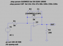
Tried figuring out baffle step. There's a simple circuit with an RC shunt at the input of a unity-gain buffer opamp, but I thought it would be more "interesting" to have filter components in the feedback loop, so I found something from Doug Self's book.
The equations he has given didn't seem to make sense with the response curve shown, so I tried some simulation. I found the curve shape I wanted, and played with stepping through values of the gain-control resistor and the frequency-determining capacitor. Simple formulae about an Fc didn't seem to make sense, they weren't correlating very closely or obviously with the shapes of the graphs. So I decided to leave the graphs as graphs. I'll let the builder choose the size and frequency of the shelf.
This is one part of the circuit which will need tweaking based on listening tests even after the speaker is built, because it depends so much on individual listening tastes and on room response. So, I decided to make it flexible for the builder to change the gain control resistor value, and the frequency-determining capacitor.
Shelf height control
The resistor value needs to be 5K, or 8.2K or 18K, to give you a 6dB, or 4dB, or 2dB shelf. That's enough control to meet pretty much any situation I've encountered. There's a 4-way DIP switch to let the builder choose this. The fourth "way" in the switch lets you completely eliminate the resistor, which means no baffle step at all. This can be used for experiments to "take BSC out" and see how it sounds. (If you really knew from the beginning that you don't want any BSC, you would not populate the resistors and capacitors and DIP switches at all to begin with.)
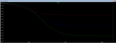
Shelf knee frequency control
I've plotted graphs to let the builder choose -3dB points from 1025Hz to about 100Hz, assuming that he's opting for a 6dB shelf size. Basically, it made more sense to me to see the graphs and "visually" decide what to try. From my table, the builder can choose the frequency determining capacitor. I've allowed for two additional capacitors in parallel, and a 2-way DIP switch, so that the builder can add a bit more capacitance and lower the knee frequency and try it out in his actual listening environment.
The equations he has given didn't seem to make sense with the response curve shown, so I tried some simulation. I found the curve shape I wanted, and played with stepping through values of the gain-control resistor and the frequency-determining capacitor. Simple formulae about an Fc didn't seem to make sense, they weren't correlating very closely or obviously with the shapes of the graphs. So I decided to leave the graphs as graphs. I'll let the builder choose the size and frequency of the shelf.
This is one part of the circuit which will need tweaking based on listening tests even after the speaker is built, because it depends so much on individual listening tastes and on room response. So, I decided to make it flexible for the builder to change the gain control resistor value, and the frequency-determining capacitor.
Shelf height control
The resistor value needs to be 5K, or 8.2K or 18K, to give you a 6dB, or 4dB, or 2dB shelf. That's enough control to meet pretty much any situation I've encountered. There's a 4-way DIP switch to let the builder choose this. The fourth "way" in the switch lets you completely eliminate the resistor, which means no baffle step at all. This can be used for experiments to "take BSC out" and see how it sounds. (If you really knew from the beginning that you don't want any BSC, you would not populate the resistors and capacitors and DIP switches at all to begin with.)
Shelf knee frequency control
I've plotted graphs to let the builder choose -3dB points from 1025Hz to about 100Hz, assuming that he's opting for a 6dB shelf size. Basically, it made more sense to me to see the graphs and "visually" decide what to try. From my table, the builder can choose the frequency determining capacitor. I've allowed for two additional capacitors in parallel, and a 2-way DIP switch, so that the builder can add a bit more capacitance and lower the knee frequency and try it out in his actual listening environment.
- 22n: 1025Hz
- 33n: 675Hz
- 47n: 475Hz
- 68n: 330Hz
- 100n: 220Hz
- 150n: 150Hz
- 220n: 100Hz
Attachments

Last edited:
Input stage schematic
I'm thinking of using this circuit for the input stage.
Though I've shown the XLR, RCA and DPDT switch as symbols here, they'll be removed from the final schematic file because they'll be off-board, and I'll just put a 1x4 connector on the board edge to get the wires in.
Nothing much new and innovative here. Values shown are "normal", but the feedback resistor can be increased if more gain is needed here, if the later stages don't have much gain and the builder wants to run the circuit hot to increase SNR. The choice of non-polar electrolytic capacitors of a large value for DC blocking, as shown, may not find much support from audiophiles who believe all electrolytic capacitors are Very Bad.
Attachments
Last edited:
@ tcpip
Thanks for the comprehensive project description!
One thing I'd like to suggest: To seize the full potential of this design and avoid limitation right from the input onwards, is to digg deeper into the "unbalancing" of the balanced input signal! To achieve a "really" balanced input (i.e. which is not referring to ground!) and to maximise the common mode rejection capability of a balanced line connection, it is very advisable and actually wide common practice to use the "classic" 3-OpAmp Instrumentation Amp circuit! Besides having a clean unbalancing design, you can then connect the unbalaced/Cinch input conncetions in any order wanted/needed (i.e. shield or signal on any of the two inputs, even switchable to reverse phase 😉).
so far my 2 cents worth...
Regards,
Winfried
Thanks for the kind words. [emoji2]@ tcpip
Thanks for the comprehensive project description!
One thing I'd like to suggest: To seize the full potential of this design and avoid limitation right from the input onwards, is to digg deeper into the "unbalancing" of the balanced input signal! To achieve a "really" balanced input (i.e. which is not referring to ground!) and to maximise the common mode rejection capability of a balanced line connection, it is very advisable and actually wide common practice to use the "classic" 3-OpAmp Instrumentation Amp circuit! Besides having a clean unbalancing design, you can then connect the unbalaced/Cinch input conncetions in any order wanted/needed (i.e. shield or signal on any of the two inputs, even switchable to reverse phase 😉).
so far my 2 cents worth...
Regards,
Winfried
I'm going by Doug Self's extensive discussion on various balanced input circuits here. The 3-opamp in-amp topology is a classic. Another popular solution is to use a purpose-built That chip. But in normal domestic audio-frequency signals, at 100mV or thereabouts, not tiny signals like a fraction of a mV, with cables just a few metres long, Self says this single-opamp topology is good enough, and so I'm going with that.
This is not a world's best gold medal winner circuit. I want it to be more than good enough for "normal" situations that's all. If I build it and later face problems, I can always design a version with a different input circuit later. Designing and building have become easy these days.
And...?Take a look at Linkwitz/Reailly crossover filters.
They keep phase shift to 360 degrees.
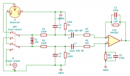
I completed the first complete draft of the schematic. PDF attached. This will almost certainly change, but most parts will probably remain the same.
After the input block is the BSC block. The builder can choose whether to apply it globally or just to the low-frequency branch. After the BSC come the two branches.
The HF branch has a sequence of two HPF blocks, letting you do a 4th order slope. Then comes a notch filter, and finally the output block with gain control. The LF branch gets an optional LT or biquad equaliser block, which can be bypassed, followed by two LPF blocks, and finally a variable gain output block.
The LPF blocks have voltage divider options at their inputs, to allow the builder to shed some gain if needed. In an active filter, optional gain control facilities at various points in the chain are always nice to have, specially if you can omit them completely if you don't need them. Since the HPF blocks do not start with a series resistor, there is no easy way to add voltage dividers at their inputs.
Both the HPF and LPF filters have provision for two capacitors in parallel to get values close to what one may need, and two resistors in series for the same reason. The issue here is not whether one can get 1% tolerance components -- it's about whether you can get components of the right value, specially if you, like me, will use a tuned, non-standard Q for your filters and this may mean non-standard, one-off component values and non-standard stage gains.
Both the branches have the output blocks configurable to be inverting and non-inverting as needed. And choosing the right input and feedback resistors will let us control gain. Whether you will need an inverting or non-inverting output stage will depend on what the preceding blocks are doing to the signal. And this story changes depending on which optional blocks the builder includes in each branch. For instance, the BSC is an inverting stage, and your choice of whether you want BSC global or just for the low-frequency branch will decide what is the signal polarity of the high-frequency branch. And so on. So, a selectable inverting-or-noninv output stage is a very useful block.
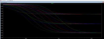
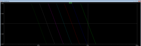
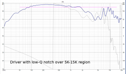
The last bit was the notch filter. I have one spare opamp, so I was looking at any notch filter circuits which wouldn't be terribly narrow (or high-Q) and would need one opamp. So, the Bainter notch was out, though it's supposedly very easy to configure -- it needs three opamps. So I picked this one, borrowed from the Baxandall tone control, actually. This gives me a wide, low-Q notch, which may be useful to suppress cone breakup regions of midbass or midrange drivers.
One doesn't really know how useful a notch filter is till one applies it to some real world bad boys from speaker drivers. So I picked the Dayton RS180 aluminium cone midbass driver, famous for high performance and vicious cone breakup. Loaded the driver SPL curve into VituixCAD and tried applying the notch filter. I tweaked the parameters to get the notch to spread just right, across the cone breakup region. I've attached the SPL curves here with and without the notch filter. You can decide whether this kind of notch is useful. I thought it could be handy in some cases. I'm still not done experimenting with notch circuits -- there's one more I have found, which may be useful. Will post results once the sims are done.
As you can see, many of the components do not have values. When my design is done, some of them will get values, others will remain blank and I'll write a note explaining where to get values from.
After the input block is the BSC block. The builder can choose whether to apply it globally or just to the low-frequency branch. After the BSC come the two branches.
The HF branch has a sequence of two HPF blocks, letting you do a 4th order slope. Then comes a notch filter, and finally the output block with gain control. The LF branch gets an optional LT or biquad equaliser block, which can be bypassed, followed by two LPF blocks, and finally a variable gain output block.
The LPF blocks have voltage divider options at their inputs, to allow the builder to shed some gain if needed. In an active filter, optional gain control facilities at various points in the chain are always nice to have, specially if you can omit them completely if you don't need them. Since the HPF blocks do not start with a series resistor, there is no easy way to add voltage dividers at their inputs.
Both the HPF and LPF filters have provision for two capacitors in parallel to get values close to what one may need, and two resistors in series for the same reason. The issue here is not whether one can get 1% tolerance components -- it's about whether you can get components of the right value, specially if you, like me, will use a tuned, non-standard Q for your filters and this may mean non-standard, one-off component values and non-standard stage gains.
Both the branches have the output blocks configurable to be inverting and non-inverting as needed. And choosing the right input and feedback resistors will let us control gain. Whether you will need an inverting or non-inverting output stage will depend on what the preceding blocks are doing to the signal. And this story changes depending on which optional blocks the builder includes in each branch. For instance, the BSC is an inverting stage, and your choice of whether you want BSC global or just for the low-frequency branch will decide what is the signal polarity of the high-frequency branch. And so on. So, a selectable inverting-or-noninv output stage is a very useful block.
The last bit was the notch filter. I have one spare opamp, so I was looking at any notch filter circuits which wouldn't be terribly narrow (or high-Q) and would need one opamp. So, the Bainter notch was out, though it's supposedly very easy to configure -- it needs three opamps. So I picked this one, borrowed from the Baxandall tone control, actually. This gives me a wide, low-Q notch, which may be useful to suppress cone breakup regions of midbass or midrange drivers.
One doesn't really know how useful a notch filter is till one applies it to some real world bad boys from speaker drivers. So I picked the Dayton RS180 aluminium cone midbass driver, famous for high performance and vicious cone breakup. Loaded the driver SPL curve into VituixCAD and tried applying the notch filter. I tweaked the parameters to get the notch to spread just right, across the cone breakup region. I've attached the SPL curves here with and without the notch filter. You can decide whether this kind of notch is useful. I thought it could be handy in some cases. I'm still not done experimenting with notch circuits -- there's one more I have found, which may be useful. Will post results once the sims are done.
As you can see, many of the components do not have values. When my design is done, some of them will get values, others will remain blank and I'll write a note explaining where to get values from.
Attachments

Last edited:
Work continues at the usual snail's pace. I took Winfred's feedback to heart and re-visited the input stage design. I realised that his idea of a 3-opamp input stage is far better than my single-opamp design, in terms of lower SNR. I decided to incorporate that. Then I chanced upon https://www.sparkfun.com/products/14002 and I'm now wondering whether it's better to just use it and thus take the entire balanced input circuitry off-board. With this module, I can do away with a complicated input stage and just revert to a single opamp. The module also has a convenient set of switched inputs, which means I can hook up an RCA socket which will feed my circuit when there is no TRS jack inserted in the socket. This makes it easy to short the cold signal pin to audio-gnd only when using unbalanced inputs, and decouple them when I'm going balanced. The module also has all the auxilliary passive components needed to protect the input from RFI and ESD, which is nice.
On the crossover front, I'm wondering whether I should add an all-pass filter stage to time-align the mid+tweet with the woofer after the two signals are separated out.
On the crossover front, I'm wondering whether I should add an all-pass filter stage to time-align the mid+tweet with the woofer after the two signals are separated out.
Realised a basic error. I don't need a notch filter of any kind in the HF branch.
If I'm using the active xo for a woofer-to-rest split in a 3-way design, then the LF output will go to the woofer, till say, 200Hz. The HF output will carry 200Hz to 20KHz, and will feed an amp channel which will then feed a passive xo for the mid-to-tweeter split. In that scenario, having a notch will not help me tame cone breakups in the mid driver, because the notch in the HF path will mess with the entire frequency range which is going to the mid+tweeter. If I need a notch at all, I'll need it after the mid and tweeter freq ranges have been split by the passive xo. So, a notch in the HF path of the active xo will be unusable.
If I use the active xo for a pure 2-way speaker instead, like my Asawari MTM designs, then the LF will carry the entire freq range for the midbass, say, 20Hz to 2.5K. The HF path will carry 2.5K to 20K. Once again, putting a notch filter in the HF path will be of no use, because I've never had to wrestle with a peak in the SPL curve of a tweeter. I have only needed to fight the peaks in the cone breakups of midbass drivers in 2-way designs. Therefore, for the notch to be useful at all, it'll need to be in the LF path, not the HF path.
So, I'll either not need any notch filter ever, or I'll need it in the LF path of the active xo.
Stupid mistake.
By filter capacitors do you mean those that set the frequency response? If so do you know not to use type 2 ceramics for this purpose? SMT film caps are very limited as many dielectrics melt at soldering temperatures, so there are no PS or PP SMT capacitors. PPS is available and is quite a reasonable choice (low distortion, good stability), but availability of anything but E6 values is limited, and case size will depend on value and voltage, you can't just pick 1206 and hope they will all fit that footprint. For smaller values of capacitance type 1 ceramics (C0G or NP0) are fine however, they are linear and stable.SMD capacitors?
I'm not comfortable soldering SMD parts, but I think I'll use SMD for the filter capacitors, because the through-hole high quality box capacitors can be as large as 13mm x 6 mm, which is really too big when I'm going to use so many of them. So I'm thinking of using 1206 SMD footprints, the biggest there is in SMD.
Thanks big-time, I didn't know this. And in any case, I was veering towards a mix of SMD and THT. I have now begun to think that everything else in the circuit can be SMD, but the components which the DIYer may need to experiment with need to be THT. Your insights seals the deal, I'll go with THT for the frequency-setting capacitors and resistors.
Can you also suggest what sizes of box caps to make provision for on the PCB, for the 1% high stability low distortion caps? I'll just use those footprints.
Input stage schematic
I'm thinking of using this circuit for the input stage.
Though I've shown the XLR, RCA and DPDT switch as symbols here, they'll be removed from the final schematic file because they'll be off-board, and I'll just put a 1x4 connector on the board edge to get the wires in.
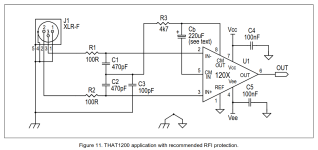
I've decided to replace the opamp-based input with a THAT 1206. The application note gives this circuit:
I'll just use this unless one of you tells me it needs work.
I wonder what happens if I connect a single-ended input signal to a THAT chip, i.e. I connect pin 3 (IN+) of the chip to the RCA socket's centre pin, pin 2 (IN-) to the RCA socket's "ring". If the chip takes it and gives me sensible single-ended output, I'll be able to provide an XLR and an RCA socket for the input, and I can use one of those TRS sockets which have switches which route different signals to the chip based on whether a TRS jack is inserted or not.
Attachments
Last edited:
I looked up Mouser for PPS box caps of sizes 10nF to 1uF (based on the range of values I had arrived at for my BSC block). I'll probably need 22nF to 220nF.By filter capacitors do you mean those that set the frequency response? If so do you know not to use type 2 ceramics for this purpose? SMT film caps are very limited as many dielectrics melt at soldering temperatures, so there are no PS or PP SMT capacitors. PPS is available and is quite a reasonable choice (low distortion, good stability), but availability of anything but E6 values is limited, and case size will depend on value and voltage, you can't just pick 1206 and hope they will all fit that footprint. For smaller values of capacitance type 1 ceramics (C0G or NP0) are fine however, they are linear and stable.
In any case, I looked up the box cap sizes. Lengths vary from 7.2mm to 13mm, lead spacing 5mm to 10mm, and this is not high accuracy caps -- tolerance varies between 2.5% and 10%. For BSC, I suspect this accuracy is ok, but for the actual LPF/HPF blocks, I will need 1-2%, I am guessing.
So, for the BSC block, I guess I've got package sizes, but I'll have to see what to do about the more accurate locations.
What voltage rating of caps should I look at? I was checking out 35-50V.
Instead of the THAT chip, there are more modern chips like the LME49724 (or its successor, the OPA1633) and the INA165x. I am thinking of using the INA 1651 single-channel chip. This circuit for a 2-ch line receiver (INA1650) is given:I've decided to replace the opamp-based input with a THAT 1206.
There's this circuit example too, using the INA 1650. I will not need the output-side capacitors etc, because in my case, the single-ended signal will feed the active xo.
It may be a good idea to add the ESD and RFI suppression components to the input tracks before the IC.
None of these new chips are available in DIP packaging, only in SMT.
Last edited:
In the BTSB "Best Thing since Sliced Bread" balanced-input board, this is what is happening after the differential amplifier:

After the differential amplifier IC, there is an opamp being used to convert the balanced output to single-ended. Is this necessary? Is this being done just to drive more output current? If the output current from the differential amplifier is adequate to drive the balanced outputs, is it not necessary to drive the unbalanced outputs too?
After the differential amplifier IC, there is an opamp being used to convert the balanced output to single-ended. Is this necessary? Is this being done just to drive more output current? If the output current from the differential amplifier is adequate to drive the balanced outputs, is it not necessary to drive the unbalanced outputs too?
Attachments

Seems like this could work?
https://www.hypex.nl/products/amplifier-families/fusion-amplifier-family/
https://www.hypex.nl/products/amplifier-families/fusion-amplifier-family/
Oh, I love those products and am building using them. But for many situations, I want to build a pure analog solution without any DSP, and use my own amp modules. For instance, I want to build active speakers using chip amp modules, like the 3886DR from Neurochrome. One module per driver.
- Home
- Source & Line
- Analog Line Level
- An analog active crossover for embedding in speakers