I would like to build a push-button solid state input selector with lots of inputs. Never done this before after having terrible experience with a Quad pre-amp about 25 years ago. I think it used 4066 c-mos switches and was quite un-reliable.
What was wrong with it? Did the 4066 get driven into latch-up by large input signals and self-destruct, or was it some other issue?
You can much reduce the risk of self-destruction after latch-up by using a power supply that can only deliver little current, for example something with resistors, Zener diodes and the bare minimum decoupling.
Oh god yes, 4000 series latch-up, a nightmare, its all coming back! I think Horovitz and Hill had a few war stories about that.
Even with much more modern chips it is a problem sometimes. The local broadcasting station here used to have a computer with a video digitizing card that was connected to a surveillance camera, the card had a Conexant Fusion chip. The supplies of the computer and camera and the video cable had to be connected in a very specific order, otherwise the video digitizing card would not survive. I've seen a blown-up card where the Conexant Fusion IC had a burst in its package, so I think it must have been latch-up.
Last edited:
Thanks all, again. I have never played with arduino and don't really want to at present. However, the lo temp solder paste looks worth investigating.
My experience with the Quad control unit years ago was a "simple" repair job where the customer could not select inputs correctly. - I was staggered that a situation could arise where an otherwise excellent product would be totally screwed up by input selection. - Tape on phono, different channels swapped, like a brain hemmorrhage. But, to repair the thing I found it depended on the actual "brand" of IC that it would work on. I think it was RCA, but whatever, it certainly was enough for me to steer well clear of S-S switching in any of my own designs & has been so ever since.
Switched Relays, (thanks OlegSh & synonymous), may be worth investigating, but the added wiring complexity warrants PCB design, which for me, time-wise is a negative, but, does anyone know of, - or have a template for an edge connector where the PCB edge itself forms half of the connector. I have plenty of gold-plated multi-pin edge connector parts spaced at .1" (& .15"). - It would be nice just to be able to select a block of connections say up to 30 odd & just delete what is not needed when designing a PCB. - Express PCB which I have, does not have ready template for this.
For low level signals, I found the Analog Devices switches virtually noiseless and contributed nothing to THD%. If you need help with code I have some routines for their switches and rotary encoders, displays etc, if you are going to use one of the Arduino platforms.
Electronic input switches certainly enjoy a reputation for needing good input protection if you do not want them to fail. When used without input buffers, it is not uncommon to see 2k2 input series resistors. But as said, you really do want buffers. Even if it's just a bunch of (NJM)4558s. Minimal output loading, slew rate still adequate, minimal bypassing requrements.
...
Switched Relays, (thanks OlegSh & synonymous), may be worth investigating, but the added wiring complexity warrants PCB design, which for me, time-wise is a negative, but, does anyone know of, - or have a template for an edge connector where the PCB edge itself forms half of the connector. I have plenty of gold-plated multi-pin edge connector parts spaced at .1" (& .15"). - It would be nice just to be able to select a block of connections say up to 30 odd & just delete what is not needed when designing a PCB. - Express PCB which I have, does not have ready template for this.
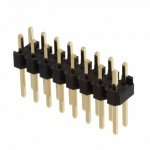
I would not recommend using board edge connector with printed pins for a DIY project. It will make your PCBs too expensive because you will need gold finish for wear resistance and reliable contact and an edge chamfer to ensure easy insertion. To wire my boards I use ribbon cable with 2-row pin header (see examples below). I place the selector PCB right next to the inputs and control circuitry somewhere else. This is cheap, simple, reliable and takes no more space than a board edge connector with printed pins.
Regards,
Oleg
Attachments

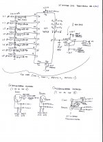
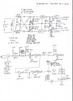
Attached are the schematics of a simple eight-to-one audio multiplexing circuit I built in 2011. It is controlled from a switching output of a mixing desk that works as a momentary switch; every time a button is pushed on the desk, the multiplexer switches to the next input. As it is a balanced stereo circuit, the part with the HEF4051 and 1/2 OPA2134 was built four times.
The OPA2134 buffer ensures that the on resistance variations of the electronic switches don't generate much distortion. The 15 pF capacitor spoils this a bit, I included it to remember the old voltage while the 4051 is being switched (break before make, using the enable input).
The 470 ohm-220 pF filters suppress any picked-up RF signals, but also limit the current that could flow into the inputs in case a signal goes beyond +7.5 V or -7.5 V. The 4000-series ICs are supplied from a Zener-stabilized supply with little decoupling to minimize the risk of anything getting damaged in case the input current should still be enough to trigger latch-up.
By the way, the 33 V Zeners were needed because the supply transformer has an unusually large ratio between the output voltages without and with load. Under worst-case conditions, the voltage could get a bit higher than the 35 V that the voltage regulators can handle.
Attachments
I think Muses do a solid state audio selector that runs off +-15V.
There’s also another crowd that does them and they were/are used in some of the Cambridge Audio stuff - so Doug Self would hav3 presumably approved.
I tried to find the data sheets on my iPad library but must have deleted them.
There’s also another crowd that does them and they were/are used in some of the Cambridge Audio stuff - so Doug Self would hav3 presumably approved.
I tried to find the data sheets on my iPad library but must have deleted them.
I’ve used the 4051 in industrial applications switching uV through to volt signals with great success - if you follow a few very basic rules they work really well. The most important 2 points are
1. limit the current into the switch and/or ensure the signal voltage does not exceed the supply rails.
2. Keep the digital control signals within the supply rails. If you go to the supply rails or higher, they distort. I found this out the hard way switching uV signals where I got non-linearity issues.
The integrated ESD protection diodes do a good job, but they are ‘leaky’ as they approach forward conduction and cause linearity problems.
Last edited:
That's interesting... I wouldn't have thought of issue 2.
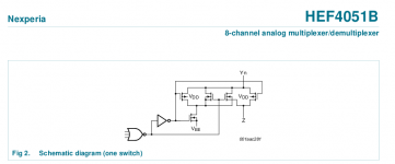
According to https://assets.nexperia.com/documents/data-sheet/HEF4051B.pdf , see the attached figure, the bulk of the pass gate NMOS is switched to the Y terminal when a switch is on, presumably to reduce on resistance and on resistance variations. Apparently the HEF4000 ICs are made in a process with N-type substrate, or at least that is my educated guess seeing that all PMOS bulks are hardwired to the supply while NMOS bulks are connected to different nodes.
As a result, you probably get substrate coupling issues whenever any terminal goes enough above the positive supply to cause forward conduction. The ESD diodes to VDD are probably series of N+ and P+ stripes placed straight in substrate. When an input goes too high, its anode, the substrate and the P-type source and drain regions of any PMOS form a giant lateral PNP transistor. The ESD diode anode then acts as the emitter, the substrate as the base and the sources and drains of all PMOS transistors as collectors.
Attachments
If you need help designing a PCB, I can help you.
Draw up a scheme and give me some specs for mounting etc..
You can send the files to JLCPCB and get a handful of boards for cheap.
Careful for the addiction, I just tossed about 65 lbs of unused boards the other day.
S
Draw up a scheme and give me some specs for mounting etc..
You can send the files to JLCPCB and get a handful of boards for cheap.
Careful for the addiction, I just tossed about 65 lbs of unused boards the other day.
S
That's interesting... I wouldn't have thought of issue 2.
According to https://assets.nexperia.com/documents/data-sheet/HEF4051B.pdf , see the attached figure, the bulk of the pass gate NMOS is switched to the Y terminal when a switch is on, presumably to reduce on resistance and on resistance variations. Apparently the HEF4000 ICs are made in a process with N-type substrate, or at least that is my educated guess seeing that all PMOS bulks are hardwired to the supply while NMOS bulks are connected to different nodes.
As a result, you probably get substrate coupling issues whenever any terminal goes enough above the positive supply to cause forward conduction. The ESD diodes to VDD are probably series of N+ and P+ stripes placed straight in substrate. When an input goes too high, its anode, the substrate and the P-type source and drain regions of any PMOS form a giant lateral PNP transistor. The ESD diode anode then acts as the emitter, the substrate as the base and the sources and drains of all PMOS transistors as collectors.
Sorry, I meant to write that the sources and drains of all PMOS transistors and the switched bulk of the pass gate NMOS act as parasitic collector. That switched bulk is probably larger and more effective as a collector than the PMOS drain/source stripes.
Thanks MarcelvdG, but I will pass for the moment.
OlegSh, you are quite correct about plug-in PCB's, BUT, - over 40 years ago I simply used a solder coated board & lightly chamfered the edges. They were plugged into Gold Plated sockets with a spray of cleaner lubricant. I have used this scheme ever since with no problems.
We were only doing relatively small runs but had no trouble at all, and, it was wonderful being able to swap boards around instantly for checking, comparing & fault-finding. Some of these original 40 year old Hi-Fi amplifiers are still giving good service to-day & I have one in my hobby room. I have no desire to change, particularly when I have a good stock of parts for making up the sockets with gold-plated pins.
Now, synonymous, thanks very much for your kind offer. - I don't relish PCB layout design and these days I don't have other people to do it for me ! - I do have express PCB, though have not used it yet, but don't know of JLCPCB so am guided by you. Sounds interesting though, as I have lots of ideas (crazy thoughts), about comparing different RIAA schemes to complement my hundreds of good classical LP's.
- Home
- Source & Line
- Analog Line Level
- Solid state switching