Yes that is the question. I just don't see how it would change. The amount of EC improvement is stable across conditions and circumstances, at least so far in my tests. The question is how to confirm it stays the same when the main amplifier is not highly distorting. All of my tests so far seem to indicate that the performance bonus of the EC is static. Also knowing how it works, I just don't see how it would change. But of course I'm not willing to post a schematic yet so we'll ignore that concern. I don't know how to test this on an already ultra high performing amplifier because I can't see the result.
Also because I know people are going to not read before posting as is typical, I'll post a direct link to my view able results here I got -290 dB Distortion
It's sad that I have to do this.
Also because I know people are going to not read before posting as is typical, I'll post a direct link to my view able results here I got -290 dB Distortion
It's sad that I have to do this.
Last edited:
Here is an LT1364 putting 12.9v p-p into 100 ohms

Here is the same after applying EC

You appear to drop 0.25V RMS from the output in the second chart. That would be enough to drop the distortions to those levels without any "EC system".
Clipping distortions have a very abrupt threshold, in particular for an opamp stage, I'll let you figure out why. Redo the experiment with the output levels exactly matched.
Unfortunately I've been trying for a long time to turn this into a sellable product so I want to sell a few before I post a schematic.hellokotty123: I may have overlooked it already having been addressed somewhere in this thread, but can you provide or point us to some schematic or paper on the operating details of the EC circuit you are employing? Thanks.
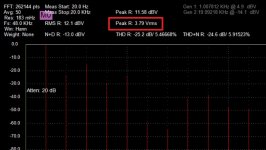
You're right, that's only because I averaged them for different lengths of time though. The Vrms changes per tick of averaging until it levels out. The voltage was definitely the same. The current conditions I'm putting the LT1364 under are waay outside of spec. It's supposed to be able to handle 50ma into 150 ohms, I'm driving it with over 100ma into 100 ohms. The voltage discrepancy does not change the result, the opamp distorts wildly way before this point. Even if I bring the output down to 4.3vp-p which is as low as the oscillator will go at this gain, the distortion is still relatively high as shown here.You appear to drop 0.25V RMS from the output in the second chart. That would be enough to drop the distortions to those levels without any "EC system".
Clipping distortions have a very abrupt threshold, in particular for an opamp stage, I'll let you figure out why. Redo the experiment with the output levels exactly matched.

Here is the new result with shown matching vrms as you requested. I even let the oscillator settle in for 5min between tests to be sure. Pre EC

Post EC

Again, the post EC result is below the capability of the analyzer to display. The harmonics you see are those of the analyzer itself.
Last edited:
hellokotty123: I may have overlooked it already having been addressed somewhere in this thread, but can you provide or point us to some schematic or paper on the operating details of the EC circuit you are employing? Thanks.
You missed the other threads, that's not going to happen.
But I asked before where does the -150dB come from maybe you could just sketch what you see on the screen. The QA401 as you are using it will never display better than -120dB noise floor. The display gives you useful information BTW the 0dB is actually -20dB THD (~10%) which might be barely visible, you have just moved the reference level around.
Mr. Scott.
As I've said I have Cordell's Distortion magnifier which allows me to see down to -150db after conversion. Basically what I try to do is let one of the harmonics hit close to the zero DB point and then I take the post EC reading through the distortion magnifier and read the result.
However at the moment my 20vac wallwart is fried, I need to order a new one in order to fire up the Distortion magnifier. However, even without the distortion analyzer the distortion won't go above the noise floor no matter what I do to it unless I push it beyond it's physical capabilities.
This has been my bane for a very long time before I got the distortion magnifier roughly a year ago. Although the circuit I'm displaying here is a dumbed down version of the EC, It's roughly 60% worse than the full scale version in terms of performance and I actually think I can do even better than that, but I would need someone more experienced than I in stability compensation to achieve it.
Last edited:
Mr. Scott.
As I've said I have Cordell's Distortion magnifier which allows me to see down to -150db after conversion.
And that's all you can measure and verify, a 150dB improvement by extrapolation is probably fantasy. Also the DM does not remove the DUT's noise. A power amp at say 20dB gain would need to have unusually low noise at the settings you are using even with the DM.
Because if I've learned one thing about audiophiles, at least in the headfi market, it's that they obsess over the new "best". There's a rather long list of things I can make that are much superior to things on the market for much much cheaper than the offerings on the market. I also enjoy designing out-of-the-box audio related things that happen to also be unusually high performance. I have a huge spice library of whacky and high performance ideas but this EC thing kind of puts everything else to shame, it's in a category of its own so all my other ideas relating to amplifier design became obsolete. I just need a few marketable prototypes that I can show investors and something resembling the actual specs of the device. Unfortunately getting to that point has been a money pit.Why attempt to make something that lowers distortion to such a low level to sell if no one can measure it anyway, why not just say you have?............")
As far as practical audio improvement, after about -120db performance I haven't noticed any difference in sound as far as power amplifiers go and even that is being generous. It's the dac is where I find the big changes in sound which is where I've put my efforts for the last year into.
Hmm, well the results of the DM are showing the harmonics down to -150db. These are clear harmonics, not noise. How am I supposed to interpret this if the DM cannot work below the noise floor of the analyzer? The DM manual even says it will allow sound cards and such to reach -140+db measurement capability.And that's all you can measure and verify, a 150dB improvement by extrapolation is probably fantasy. Also the DM does not remove the DUT's noise. A power amp at say 20dB gain would need to have unusually low noise at the settings you are using even with the DM.
Also do you have an example reason to why the EC improvement would change @ -150db relative to any other point? In all of my measurements the improvement has been basically static at any point.
Last edited:
What the hell is this EC? Just build a reasonable amplifier and you have the slightest distortion. No need for voodoo.
Playing with (or rather, understanding) 'voodoo' is fun and interesting.

For many of us in DIY, it is a matter of technical curiosity. For others, it is for the fun of knowing that we've built something ourselves which has performance or features not available even on the commercial market.
The EC circuit is such an issue because it is what ostensibly enables the claimed performance level. It rightly is at the center of this discussion for that reason. It's difficult to give validity to the extraordinary performance results without knowing in detail both the test set-up and the entire circuit under test.
Last edited:
Here is the new result with shown matching vrms as you requested.
I even let the oscillator settle in for 5min between tests to be sure.
Pre EC
Post EC
Again, the post EC result is below the capability of the analyzer to display. The harmonics you see are those of the analyzer itself.
Something stinks like BS here. LT1364 can't have that high distortions at 3.79V RMS output, unless the output current limiting kicks in, or you feed the opamp at something like +/-5V or less.
In both cases, these are distortions that no EC circuit/method are going to fix, since they are outside the negative feedback loop effect. How would an EC circuit linearize the current limiting circuitry? With or without EC, the current limiting will still kick in at 50mA.
I smell here either an ignorant or a scoundrel. I'm out of this thread.
Last edited:
How am I supposed to interpret this if the DM cannot work below the noise floor of the analyzer?
One thing you could do is show a distortion measurement of your basic amplifier, and then the same measurement, same conditions, same levels, with the DM switched in. Part of the problem we have is a load of graphs where it is never clear what it actually is.
Try to think how you could best make clear what you measured and interpreted. Take it step by step, as if you are teaching a group of (smart ;-) students.
Jan
Last edited:
It's 4.3v p-p not RMS but other than that I don't know I just reduced the oscillator output to its lowest level and re-measured the distortion. I'm feeding the LT1364 +/- 8.8v and using it in inverting mode with a 1k and 10k resistor, no bypass caps before or after EC, which may actually be a reason why its a little worse than expected now that I think about it. There's quite a bit of resistance between the power source and the power pins.Something stinks like BS here. LT1364 can't have that high distortions at 4.3V RMS output, unless the output current limiting kicks in, or you feed the opamp at something like +/-5V or less.
In any case it's sort of irrelevant because the 4.3vp-p result was examplatory as a standalone test. Even if the setup is somehow compromised causing it to have a higher distortion than normal it still doesn't take away from the result of the EC as it is relative.
Uhhh, okay.I smell here either an ignorant or a scoundrel. I'm out of this thread.
I can do that once I get my DM up and running. However as far as my currents graphs go, I'm not trying to show absolute values, just relative ones. All of my graphs thus far have had a label showing the before and after EC noted above it.One thing you could do is show a distortion measurement of your basic amplifier, and then the same measurement, same conditions, same levels, with the DM switched in. Part of the problem we have is a load of graphs where it is never clear what it actually is.
Try to think how you could best make clear what you measured and interpreted.
Jan
So if A1 has X distortion before EC is applied and A1+EC has Y distortion I'm simply doing X-Y, only showing the difference and therefore relative improvement.
Last edited:
It's 4.3v p-p not RMS but other than that I don't know I just reduced the oscillator output to its lowest level and re-measured the distortion.
Really?
You'd better find out .Attachments
Why attempt to make something that lowers distortion to such a low level to sell if no one can measure it anyway, why not just say you have?............
I think it just an intellectual challenge for him to proved that you can not achieve it at your entire life
I'm reading off of the scope, not the analyzer. 4.3vp-p was the output voltage of the amplifier. Considering that the oscillator has a minimum output of around 400mv that lines up.Really?
Last edited:
You can't measure such low THD, but you can clearly hear it after death!I think it just an intellectual challenge for him to proved that you can not achieve it at your entire life
- Status
- Not open for further replies.
- Home
- Source & Line
- Analog Line Level
- -290 dB Distortion?