This attenuator concept is an attempt to address one of the most irritating flaw such devices can possess: non-monotonicity.
You can often live with imperfect linearity, limited absolute accuracy or irregular step size, but monotonicity errors are intolerable: you try to increase something, just to get the opposite response.
Monotonicity errors arise from imperfect values of the steps: if the weight of a bit does not equal the accumulated weights of lower significance bits + 1, you potentially have a non-monotonicity error if the deviation exceeds one quantum.
All forms of D to A converters can be affected, but in a regular, linear multiplying DAC, the conversion network is of the R-2R variety, meaning all values are equal, thus well matched and tracking perfectly.
With a linear in dB converter, things are entirely different: the resistors are all different, and have awkward values.
For a small number of steps like 32, it is relatively easy to guarantee monotonicity with just 1% resistors.
Unfortunately, 32 steps is too coarse to be practical: something like 100 steps at the very least is required, and the accuracy required to cover the very worst case begins to bite.
This idea uses a special two-stage architecture that guarantees the monotonicity of the largest transitions, handled by the segment section.
Problems could still arise downstream, in the interpolator section, but since it is only 5 bits, it is easily made monotonic.
The way it works is by connecting the interpolator between two taps of the segment generator: this means that the highest value of a subrange can never exceed the lowest value of the next subrange.
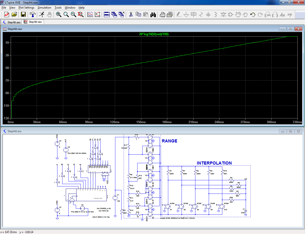
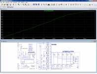
To illustrate the mode of operation, I have prepared a purely conceptual example in sim.
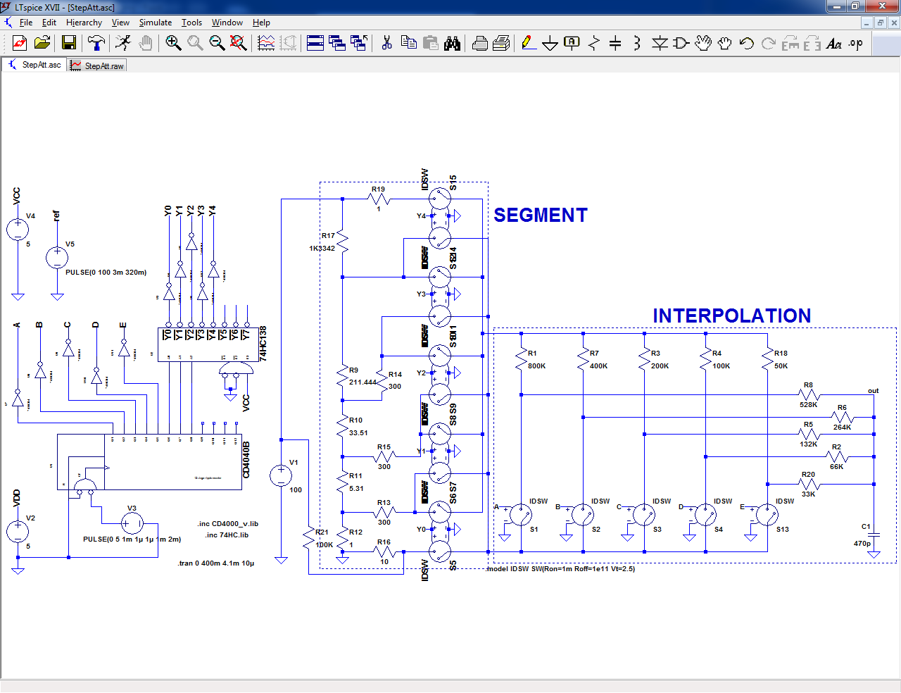
It reflects the topology and the way it operates, but a real attenuator based on these principles would be completely different:
The segment generator uses a simple resistive divider with awkward values, and the interpolator is based on a non-linear DAC having large, variable input and output impedances.
I used these expedients to simplify the sim, reduce the number of switches, etc.
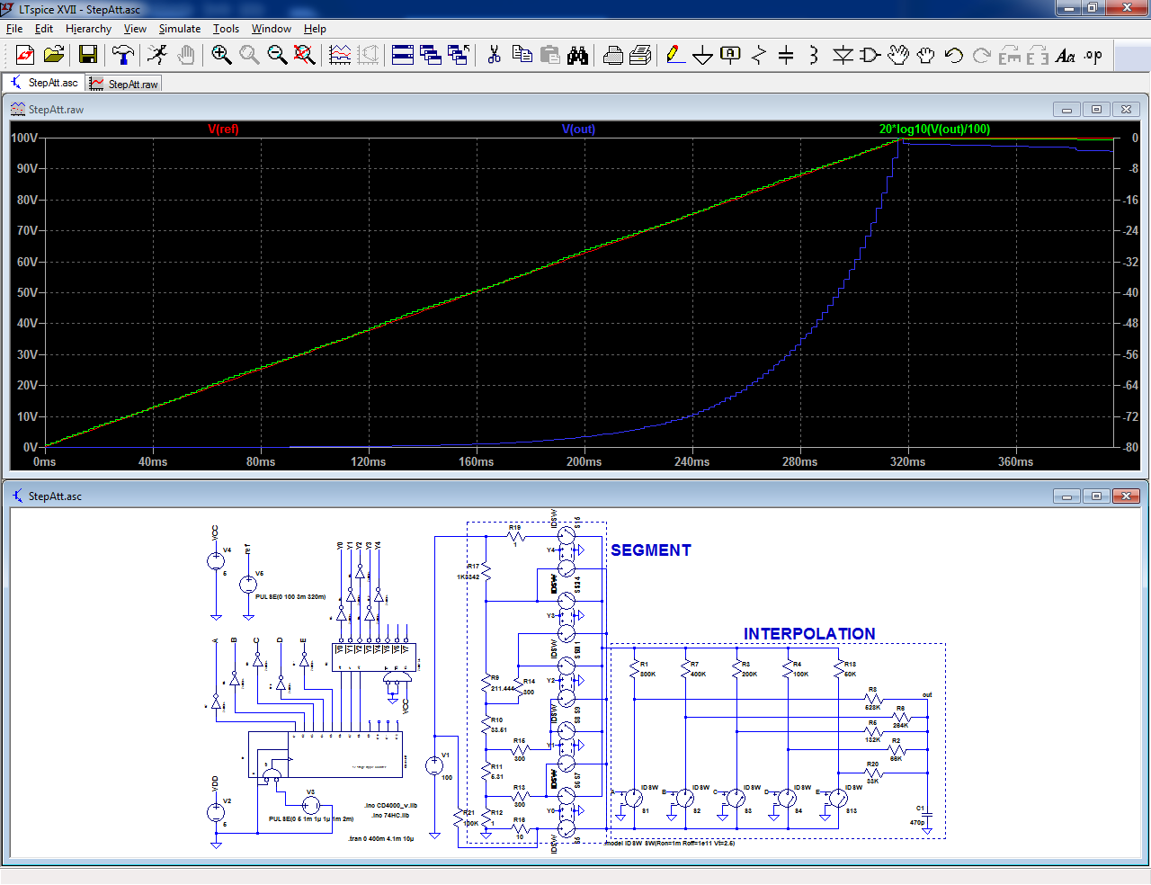
Note that all the left part serves to illustrate the operation of the circuit by scanning all the attenuation range, and C1's role is to clean up the video.
The Vref trace is just for graphic comparison.
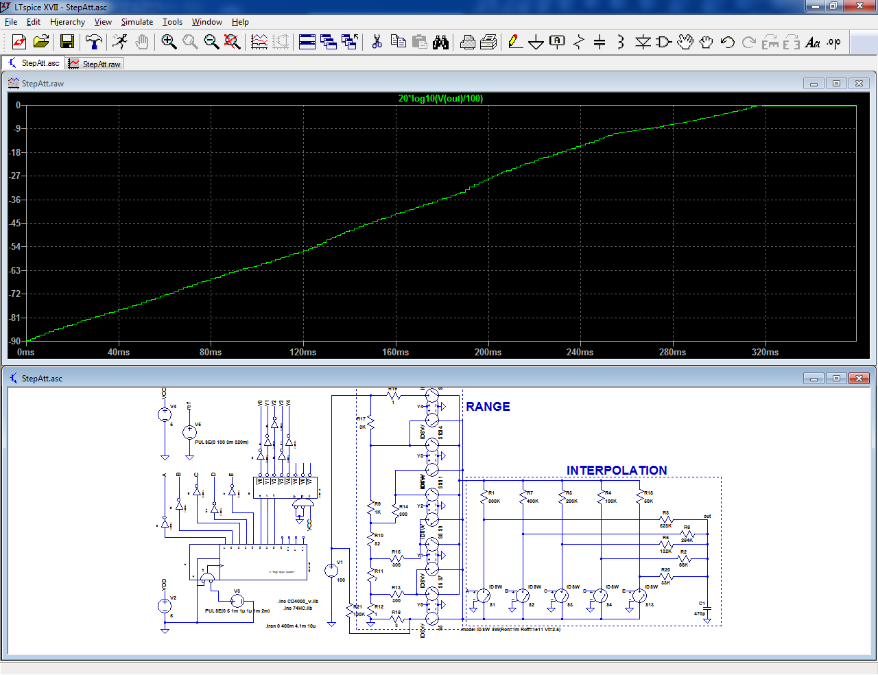
This example has been designed as a 5 bit, 5 segment, 160 x 0.5dB steps attenuator covering 80dB:
You can often live with imperfect linearity, limited absolute accuracy or irregular step size, but monotonicity errors are intolerable: you try to increase something, just to get the opposite response.
Monotonicity errors arise from imperfect values of the steps: if the weight of a bit does not equal the accumulated weights of lower significance bits + 1, you potentially have a non-monotonicity error if the deviation exceeds one quantum.
All forms of D to A converters can be affected, but in a regular, linear multiplying DAC, the conversion network is of the R-2R variety, meaning all values are equal, thus well matched and tracking perfectly.
With a linear in dB converter, things are entirely different: the resistors are all different, and have awkward values.
For a small number of steps like 32, it is relatively easy to guarantee monotonicity with just 1% resistors.
Unfortunately, 32 steps is too coarse to be practical: something like 100 steps at the very least is required, and the accuracy required to cover the very worst case begins to bite.
This idea uses a special two-stage architecture that guarantees the monotonicity of the largest transitions, handled by the segment section.
Problems could still arise downstream, in the interpolator section, but since it is only 5 bits, it is easily made monotonic.
The way it works is by connecting the interpolator between two taps of the segment generator: this means that the highest value of a subrange can never exceed the lowest value of the next subrange.
To illustrate the mode of operation, I have prepared a purely conceptual example in sim.
It reflects the topology and the way it operates, but a real attenuator based on these principles would be completely different:
The segment generator uses a simple resistive divider with awkward values, and the interpolator is based on a non-linear DAC having large, variable input and output impedances.
I used these expedients to simplify the sim, reduce the number of switches, etc.
Note that all the left part serves to illustrate the operation of the circuit by scanning all the attenuation range, and C1's role is to clean up the video.
The Vref trace is just for graphic comparison.
This example has been designed as a 5 bit, 5 segment, 160 x 0.5dB steps attenuator covering 80dB:
Attachments
The example I gave is just a plain-vanilla, linear-in-dB attenuator, but other functions are easily obtainable, always with the same guaranteed monotonicity.
In this variant, the start of curve is altered to progressively arrive at a ~ -∞ attenuation, without resorting to a mute (which is always possible by turning off all the segment switches):
Here, the slopes of individual segments have been changed:
Etc, etc...
And finally, to illustrate the robustness of the concept, here is a Monte-Carlo simulation (50 runs), with all the important components affected by a +/-2.5% tolerance:
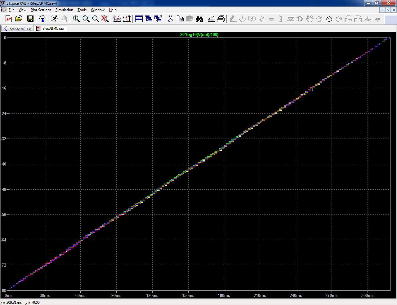
Not bad, considering the 160 steps/80 dB range: there are variations, of course, but the monotonicity is never in question
In this variant, the start of curve is altered to progressively arrive at a ~ -∞ attenuation, without resorting to a mute (which is always possible by turning off all the segment switches):
Here, the slopes of individual segments have been changed:
Etc, etc...
And finally, to illustrate the robustness of the concept, here is a Monte-Carlo simulation (50 runs), with all the important components affected by a +/-2.5% tolerance:
Not bad, considering the 160 steps/80 dB range: there are variations, of course, but the monotonicity is never in question
Attachments


We made a 16 bit DAC that way but the glitches made it useless for audio. You might want to explore the consequences of relay bounce varying from part to part, might not matter for an essentially DC application but there might be some "zipper" noise with rapid volume adjustment.
Last edited:
This design doesn't particularly target the artifacts generated during the state-change phases, thus they will be present like in any other binary-controlled attenuator, however the two-stage configuration offers an advantage in this respect: the first layer comprising the MSB's (or the equivalent in 1 out of 5 coding) is tap-controlled, meaning artifacts will be mostly absent, and the second layer only handles 16dB, meaning the largest possible artifact will be ~8dB.
In a straight 80dB design, it would reach ~40dB
In a straight 80dB design, it would reach ~40dB
- Status
- Not open for further replies.