Thanks Eddie.
Sorry, I didn't realize your eyesight wasn't too good. I'll wait for you to enlist some help.
Perhaps I can utilize some of your diode protection and DC optimization techniques to some of my op-amp circuits.
I always prefer bipolar op-amps when it comes to SQ, except for the LM4562. It's dry and lifeless sound along with its p_ss poor PSRR leave little to be desired IMHO.
Sorry Mooly. I hope we can still be buds.")
Sorry, I didn't realize your eyesight wasn't too good. I'll wait for you to enlist some help.
Perhaps I can utilize some of your diode protection and DC optimization techniques to some of my op-amp circuits.
I always prefer bipolar op-amps when it comes to SQ, except for the LM4562. It's dry and lifeless sound along with its p_ss poor PSRR leave little to be desired IMHO.
Sorry Mooly. I hope we can still be buds.
well, I have little respect for most "op amp sound" opinions
but leaving that aside, the "p_ss poor PSRR" comment is simply wrong on technical grounds
the LM4562 PSRR ds graphs closely follow the fundamental relationship for '5-pin' or dual 8 pin dominant pole op amps which simply have to have internal compensation C attached to a (or split between both) supply rail
CiteSeerX — A General Relationship between Amplifier Parameters and its Application to PSRR Improvement
shows the limit when the dominant pole compensation is referenced to a ps rail: the psrr for that rail follows loop gain
having higher open loop gain and GBW than many 'audio op amps' the LM4562 PSRR is better than most
the single NE5534 has external comp pins, can be 2-pole compensated - but I doubt it can actually do much better even on the single PSRR spec than the faster LM4562 built on a 30 years more recent complementary bipolar process by people who actually seemed to care about good audio performance
the OPA1622 has a separate gnd pin that the internal compensation is referred to - look at its ds for the decade improved PSRR that can result
but leaving that aside, the "p_ss poor PSRR" comment is simply wrong on technical grounds
...I always prefer bipolar op-amps when it comes to SQ, except for the LM4562. It's dry and lifeless sound along with its p_ss poor PSRR leave little to be desired IMHO.
the LM4562 PSRR ds graphs closely follow the fundamental relationship for '5-pin' or dual 8 pin dominant pole op amps which simply have to have internal compensation C attached to a (or split between both) supply rail
CiteSeerX — A General Relationship between Amplifier Parameters and its Application to PSRR Improvement
shows the limit when the dominant pole compensation is referenced to a ps rail: the psrr for that rail follows loop gain
having higher open loop gain and GBW than many 'audio op amps' the LM4562 PSRR is better than most
the single NE5534 has external comp pins, can be 2-pole compensated - but I doubt it can actually do much better even on the single PSRR spec than the faster LM4562 built on a 30 years more recent complementary bipolar process by people who actually seemed to care about good audio performance
the OPA1622 has a separate gnd pin that the internal compensation is referred to - look at its ds for the decade improved PSRR that can result
Last edited:
having higher open loop gain and GBW than many 'audio op amps' the LM4562 PSRR is better than most
Glad you think so jcx.
I've tried the LM4562 in numerous low gain(only 6dB) applications and found it picked up hum and other garbage from the PS whether it was a simple LM317/337 supply, a cap multiplier or a shunt supply despite using .1uF COG decoupling caps on the supply pins.
Even inexpensive JRC bipolar offerings were better at rejecting this PS garbage than the LM4562.
So I threw all my DIP-8 LM4562s in the trash and have never regretted doing so.
Keep up the good work jcx.
maybe you should look at your build and/or measurement technique
I don't see giving bad theory, counterfactuals a pass - tend to call them out as they deserve
personally I've designed Scientific Instrumentation with 3rd party Testing Lab verification - strain gage amps with load cells at the end of 50' of cabling, Av 4000 amplification, 16 bit ADC within inches of 40 MHz DSP, x86 processors with Ethernet external connections and later 100 MHz processors and USB with the strain gage amps
I frequently post here about "really good theory" - that I have hands on verified in decades of pro EE employment
my PS bootstrapped composite amps couldn't even be linearly stabilized if the Säckinger paper's theory didn't apply in the real world
Last edited:
Glad you think so jcx.
I've tried the LM4562 in numerous low gain(only 6dB) applications and found it picked up hum and other garbage from the PS whether it was a simple LM317/337 supply, a cap multiplier or a shunt supply despite using .1uF COG decoupling caps on the supply pins.
Even inexpensive JRC bipolar offerings were better at rejecting this PS garbage than the LM4562.
So I threw all my DIP-8 LM4562s in the trash and have never regretted doing so.
Keep up the good work jcx.
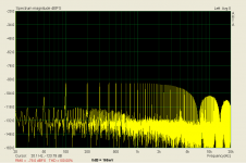
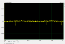
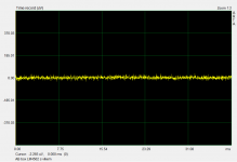
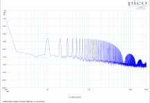
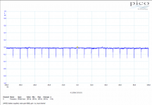
I can confirm what you are saying. I was measuring many LM4562 from different production batches in the last 10 years. First, in my special test circuit with 0dB signal gain and 80 dB noise gain. On breadboard, the 4562 was the worst in 100Hz multiples pickup, in a set of about 15 opamps. Repeated the test on double-sided PCB with shielding groundplane, the amplitude of 100Hz multiples was reduced but again the 4562 was the worst.
This year I tested it in a unity gain buffer. The problem is here again, though reduced in amplitude. You may see it in the attached measurements, both in frequency and time domain (in time domain it is in the Al box without and with top cover). The problem disappeared after placing the PCB into very well shielded Al box. It can be concluded that the LM4562 is very sensitive to air-coupled elmag. fields, regardless the datasheet perfect PSR behavior. It can be cured by perfect shielding box
.BTW, if you are interested in the opamp buffer sound, please feel free to try my new listening test. The opamp types will be disclosed in 2 weeks.
http://www.diyaudio.com/forums/everything-else/308514-another-big-opamp-listening-test.html
Attachments
Last edited:
stating PSRR is poor for the LM4562 is still simply wrong
I could believe poor differential input EMI rejection, rectification on the LM4562 input
I did consider preemptively offering RF EMI demodulation as a possible explanation for a poor observed result, if the 'observation' were given any credible supporting info
I do consider shielding, filtering necessary in all of my pro work
and we did sometimes use external switching supplies and/or switching doubler/splitter DC-DC switching converters on board - yes you do have to design high frequency rejection into the PS regulation and distribution system
PMA's post does show classic high frequency interference in the measurement - few 10s of us glitches at PS frequency (1/2 wave rectified?, no snubber?)
but the mere existence, frequency range and resolution of the LM4562 data sheet PSRR and CMRR plots make it unlikely that the problem is actually the LM4562 PSRR
for line level audio I only use FET input op amps
Last edited:
I always prefer bipolar op-amps when it comes to SQ
I think that's because of the circuits you build. That's not a bad thing though. Did you read my description of the difference between the 5532 and 2134? My opinions are based on research and testing, however humble it may be.
I pointed out that haphazard substitution of the "better" 2134 for a 5532 can actually degrade performance. I pointed out the science behind it.
If you don't like the way a 2134 sounds, it's my opinion that you're using it wrong. On the other hand, a 5532 is capable of stellar performance in some (many) circuits - in spite of its ubiquity and lack of snob appeal.
I could believe poor differential input EMI rejection, rectification on the LM4562 input
I did consider preemptively offering RF EMI demodulation as a possible explanation for a poor observed result, if the 'observation' were given any credible supporting info
I do consider shielding, filtering necessary in all of my pro work
and we did sometimes use external switching supplies and/or switching doubler/splitter DC-DC switching converters on board - yes you do have to design high frequency rejection into the PS regulation and distribution system
PMA's post does show classic high frequency interference in the measurement - few 10s of us glitches at PS frequency (1/2 wave rectified?, no snubber?)
but the mere existence, frequency range and resolution of the LM4562 data sheet PSRR and CMRR plots make it unlikely that the problem is actually the LM4562 PSRR
for line level audio I only use FET input op amps
Thank you for your input. I really do not want to create too long story, though I have collected a lot of data, made measurements at two different and distant working places, used not only sound cards but also spectrum analyzers and fast digital scopes, used decent power supplies - with the same results that confirmed that the issue was not accidental.
As you are saying, most probably undegenerated BJT input EMI demodulation enlarged (probably) by very high open loop gain and BW of the part.
Supply bypassing and snubber made no difference. There is a snubber in the power supplies.
I agree that the problem is not directly poor PSRR. The PSRR is good, if well shielded box is used, however nasty spectrum with the unshielded board may mislead to conclusion that the PSRR is bad.
In a direct comparison and same circuit, JFET input opamps showed no problems, the spectrum was clean. 4562 compared to 5532, 5532 was much less sensitive to induced EMI. However, when the 4562 PCB was inserted into well shielded aluminum box, it created a perfect line stage amplifier. But the experience with air-coupled EMI shows that the DIYers may have troubles with the LM4562, in case that the PCB design is sub-optimal and the well shielded metal case is not used, which is sometimes definitely the case.
"Adding extra electrolytic capacitors into the signal chain" is NOT a good idea in any case, methinks. They just add distortion. All capacitors in the signal path should be polypropylenes.Some audio circuits (like some tone controls and volume controls) can never be DC optimized without adding extra electrolytic capacitors into the signal chain.
"Adding extra electrolytic capacitors into the signal chain" is NOT a good idea in any case, methinks.
That's the point I was making. But you're still stuck with coupling capacitors on the output with even a few millivolts output offset. For what it's worth my "go-to" bass/treble circuit varies its output offset from around -3 to + 12 millivolts when rotating the bass control. That's with a 5532. You could put a capacitor in the leg of the potentiometer and greatly improve DC performance but my point is that it's not worth it.
All capacitors in the signal path should be polypropylenes.
For the filter capacitors it is essential to use high linearity film type caps. But for coupling capacitors, it can become impractical. This is what I use https://www.digikey.com/products/en/capacitors/aluminum-electrolytic-capacitors/58?k=&pkeyword=&s=51585&FV=fffc01ed%2C6540647%2Cffe0003a%2Cd0000f%2C1140050%2C1f140000&mnonly=0&newproducts=0&ColumnSort=0&page=1&stock=1&quantity=0&ptm=0&fid=0&pageSize=25
I built a headphone amp using big film capacitors. It's kind of silly - a tiny electronic circuit flanked by gargantuan capacitors.
Yes, the polypropylene capacitors can become unusably large. I find that the turning point comes at about 2.2uF---a polypropylene Panasonic ECW-FD2W225JB is about 17 x 11 mm and will just barely fit most applications. Above that value, you are left with three choices, really---electrolytic, non-polar electrolytic, or polyester. As Cyril Bateman pointed out in his epic paper on capacitor distortion (https://linearaudio.nl/sites/linear... 12 2002 mar2003 1uF electrolytic or film.pdf) the bipolars (such as your Nichicon MUSE) are superior to polarized caps, but “the best electrolytic, the Bi-polar type, was clearly beaten by the good metallised PET”. I have found that a fairly new product from WIMA (a PET---- MKS2B051001N00JO00) is exceptional in its combination of fairly large capacitance (10uF), small size (7x11mm), low ESR/DF (~12 times lower than the MUSE), and low distortion (< 0.0002%, -114db). It is a bit on the pricey side, as they are $3.01 each, but I have found no other cap that comes close to its performance/size.For the filter capacitors it is essential to use high linearity film type caps. But for coupling capacitors, it can become impractical.
1 - The buffer is inverting. .
It is not.
The 100k provides a DC to ground for the non-inverting input bias current. Because it is so much higher than the DC to ground from the inverting input, this will create a lot of DC offset at the output, especially with a bipolar input opamp like the 5532.
I would make it 10k the most, and also put a 10k between the inverting input and the output instead of the short. If DC offset is your concern, otherwise it ik OK the way it is.
Whoever put this together is not very experienced in opamp circuits.
Jan
It is not.
Jan
Sorry Jan, the buffer in the first post of this thread http://www.diyaudio.com/forums/analog-line-level/308415-ne5532-buffer.html#post5093861 is inverting, gain -10x.
The non-inverting buffer is in the second post of the thread.
Last edited:
The 100k provides a DC to ground for the non-inverting input bias current. Because it is so much higher than the DC to ground from the inverting input, this will create a lot of DC offset at the output, especially with a bipolar input opamp like the 5532.
I would make it 10k the most, and also put a 10k between the inverting input and the output instead of the short. If DC offset is your concern, otherwise it ik OK the way it is.
Whoever put this together is not very experienced in opamp circuits.
Jan
Re schematics in the second post of the thread, 10k input impedance is not always acceptable, so the 100k might have had a good reason. With JFET opamps, the offset by input bias current will be negligible. For LM4562, DC offset will be only about 1mV typically and with NE5532 it might be about 20mV, as the circuit is wired for gain +1. In case there is an output capacitor in the previous circuit.
. As Cyril Bateman pointed out in his epic paper on capacitor distortion (https://linearaudio.nl/sites/linear... 12 2002 mar2003 1uF electrolytic or film.pdf) the bipolars (such as your Nichicon MUSE) are superior to polarized caps, but “the best electrolytic, the Bi-polar type, was clearly beaten by the good metallised PET”. I have found that a fairly new product from WIMA (a PET---- MKS2B051001N00JO00) is exceptional in its combination of fairly large capacitance (10uF), small size (7x11mm), low ESR/DF (~12 times lower than the MUSE), and low distortion (< 0.0002%, -114db). It is a bit on the pricey side, as they are $3.01 each, but I have found no other cap that comes close to its performance/size.
I often refer to and cite Bateman's paper on capacitor distortion. And in this work, he points out how to mitigate or "swamp" capacitor induced distortion in your design. You can calculate it, you can measure it, and most important of all you can control it. And armed with this knowledge, you can design audio circuits where the electrolytic capacitors introduce virtually negligible distortion.
I avoid using those big expensive film caps unless I have to. I explicitly design so they are unnecessary if possible. I do use fancy pants film caps in my filter and tone control circuits, where non-linearity can introduce a very significant amount of distortion. I try to limit myself to 0.1 uF max if possible - size counts and so does price.
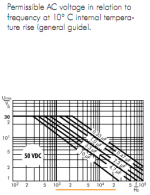
Hmmmm......hard to imagine any audio usage where a cap is going to see 50 volts DC in a solid state circuit. Tube circuits, I guess.Re dotneck335 Post #32
Check out Wima's PDF of those Caps, for suitability
Last edited:
- Status
- This old topic is closed. If you want to reopen this topic, contact a moderator using the "Report Post" button.
- Home
- Source & Line
- Analog Line Level
- NE5532 Buffer