Prasi,
What are Eagle designations of 2-pole and 3-pole screw terminals used for inputs and outputs? I am confused. There are 5mm and 5,08mm spacing screw terminals.
What are Eagle designations of 2-pole and 3-pole screw terminals used for inputs and outputs? I am confused. There are 5mm and 5,08mm spacing screw terminals.
They are available in the library con-phoenix-508
Under package name MKDSN-XXX
Always use 5.08 mm pitch.
You could also use screw terminals in library con-ptr500, package being AK500/2 or AK500/3. but these are for slightly smaller gauge wires.
Reg
Prasi
Under package name MKDSN-XXX
Always use 5.08 mm pitch.
You could also use screw terminals in library con-ptr500, package being AK500/2 or AK500/3. but these are for slightly smaller gauge wires.
Reg
Prasi
Another question regarding Eagle con-faston library. There are several 6,3mm x 0,8mm tabs in the library. Which one you use for GND, and Vcc and Vee supply connection? This is important to me when I make schematics in Eagle. I think that I can learn to use Eagle.
Another question regarding Eagle con-faston library. There are several 6,3mm x 0,8mm tabs in the library. Which one you use for GND, and Vcc and Vee supply connection? This is important to me when I make schematics in Eagle. I think that I can learn to use Eagle.
Hi Ivan,
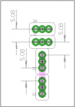
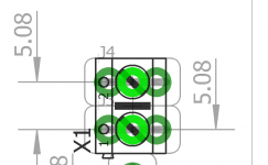
Use the attached library , in that, use the package F061.120. It is made by me and i use it for every layout. if you arrange side by side , you will have pitch spacing between 2 fastons as 5.08mm. even if you arrange one above other, pitch will still be 5.08mm. so you can fit either a faston or terminal block in those adjacent holes.
reg
Prasi
edit. secod image shows fitment of a screw terminal in the faston holes
Attachments
Last edited:
Thanks Prasi.
Welcome to eagle, its a hard road of learning ahead, but well worth the effort.
100% error free designs can be created if you you create correct schematic and have correct packages.
I will create a new thread of learning eagle and I will support that thread with replies on whatever I know about eagle. with questions on packages, layouting questions ( not checking layouts for correctness!), devices preparation, DRC, etc. Just pure using software related questions (strictly)...
Just like the thread of Mooly (on LTSpice) and put its address in my signature.
reg
Prasi
Hello Prasi,
Great design. I checked your site and i sat the adapter, may order them.
Are the eagle files for the volume design a again available.? Tks.
Great design. I checked your site and i sat the adapter, may order them.
Are the eagle files for the volume design a again available.? Tks.
I have read the tidu034 and its all about a mono channel. I am interested in stereo, so I did some reading and I found a Ti discussion, OPA1604: TIDU034 questions and possible upgrade solution - Audio forum - Audio - TI E2E support forums.  . Looks like ganging the port makes the matching and linear behavior not completely correct.
Dual gang pots seem to be up and over to 3dB mismatched,What Price For Perfection? | Nuts & Volts Magazine. Seem that matched attenuators are the best, but they are pricey.
I was wondering what was your opinion since you have designed a Baxandall control.
tks. francis
. Looks like ganging the port makes the matching and linear behavior not completely correct.Dual gang pots seem to be up and over to 3dB mismatched,What Price For Perfection? | Nuts & Volts Magazine. Seem that matched attenuators are the best, but they are pricey.
I was wondering what was your opinion since you have designed a Baxandall control.
tks. francis
The other nice theoretical advantage of the Baxandall circuit using linear pots rather than log is that the current density is constant throughout the pot's track, so that any non-linearity of resistance/resistivity in the track material cancels out (at least to a first order).
What this means in the real world is that it should work well even with cheap carbon-track pots.
I can't seem to find literature on THD measurements of log-taper pots though - perhaps this is a neglected area? Are linear taper measurable better performers for distortion?
What this means in the real world is that it should work well even with cheap carbon-track pots.
I can't seem to find literature on THD measurements of log-taper pots though - perhaps this is a neglected area? Are linear taper measurable better performers for distortion?
It does work very well.What this means in the real world is that it should work well even with cheap carbon-track pots.
I imported and modified the layout of Prasi volume control board. the layout is very similar with four changes:
1) I remove the star ground and the bottom as ground plane. Most of the signals (other than one) are on the top layer
2) There is copper pour on both layers.
3) The supply caps are closer to the opamps
4) All connectors are on the back of the board. while keeping the original on the front
5) Remove the input diode and the test load resistors
6) Added an optional output resistor, as some application notes recommend a 100 Ohms on the output. It can also be shorted, or left open if the back connectors are not used.
I will publish all files after I get the board from manufacturing.
Last edited:
Nicely done Frabor.
It might be a good idea to stitch the ground planes by vias at different places
It might be a good idea to stitch the ground planes by vias at different places
second round of changes:
1) Eliminated feedback resistors as per Resistors in the feedback of a buffer: Ask why! - Precision Hub - Archives - TI E2E support forums

2) Stitched the board and eliminated any unconnected copper. Rerouted several components to provide bigger gnd areas on top when possible.
Electronic – Should we remove unconnected copper island among connected traces – iTecTec
3) Naming error improvements and corrections.


1) Eliminated feedback resistors as per Resistors in the feedback of a buffer: Ask why! - Precision Hub - Archives - TI E2E support forums
2) Stitched the board and eliminated any unconnected copper. Rerouted several components to provide bigger gnd areas on top when possible.
Electronic – Should we remove unconnected copper island among connected traces – iTecTec
3) Naming error improvements and corrections.
Last edited:
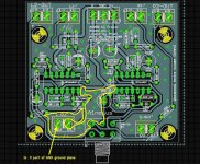
I am connecting the signal gnd to the ground plane in the other layer via a thermal. All the gnd signal connectors, both input and the two set of outputs, are connected to the ground plane. If there is a problem, please let me know.

francis.
francis.
Attachments
Last edited:
I do not know if it is a problem for this design but i always had a hum issue with 2 layers ground plane. i use now only one layer signal ground plane in my designs with no more antenna issue, if i need one layer Signal Ground plane and one Power Ground plane, they are connected separately to the PSU Ground board. With this design if you have hums problems you have to redesign the board, with two separated ground layers, you can try to connect them together at your board if you want but if you have antenna issue you can always connect them separately or with 10R resistor.
- Home
- Source & Line
- Analog Line Level
- Baxandall gain control according TI tidu34 certified design