After not quite finishing my previous preamp project I decided to change some of the goals and build a new one. This is what I want in my new preamp:
- Compact
- Volume control
- A few inputs
- Start-up mute
- Good performance
- Remote control of input selection, volume and mute
- Quality, high resolution rotary encoder
- Nice design
- Something I can actually finish and use!
In this thread I'll pull together a few separate modules I've made and include build details, pictures, BOMs, measurements etc.
I'll also post full Eagle PCB schematics and layouts so people can use or change my designs. All PCBs were made by OSHPark. If anyone wants PCBs, I may have 1 or 2 spare (as the OSHPark minimum order is 3) or just download the Eagle files, upload them to OSHPark and order them yourself 🙂

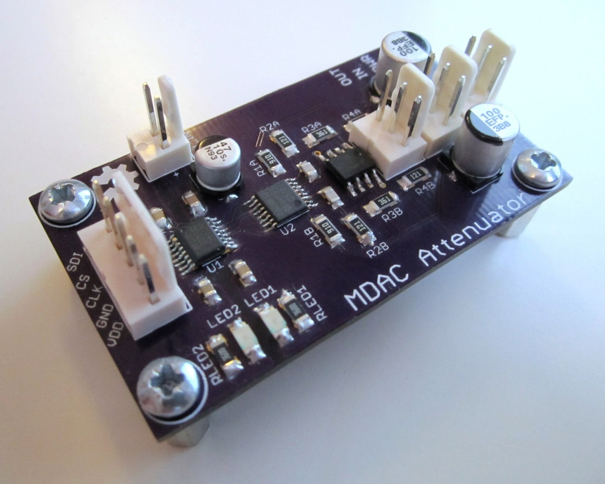
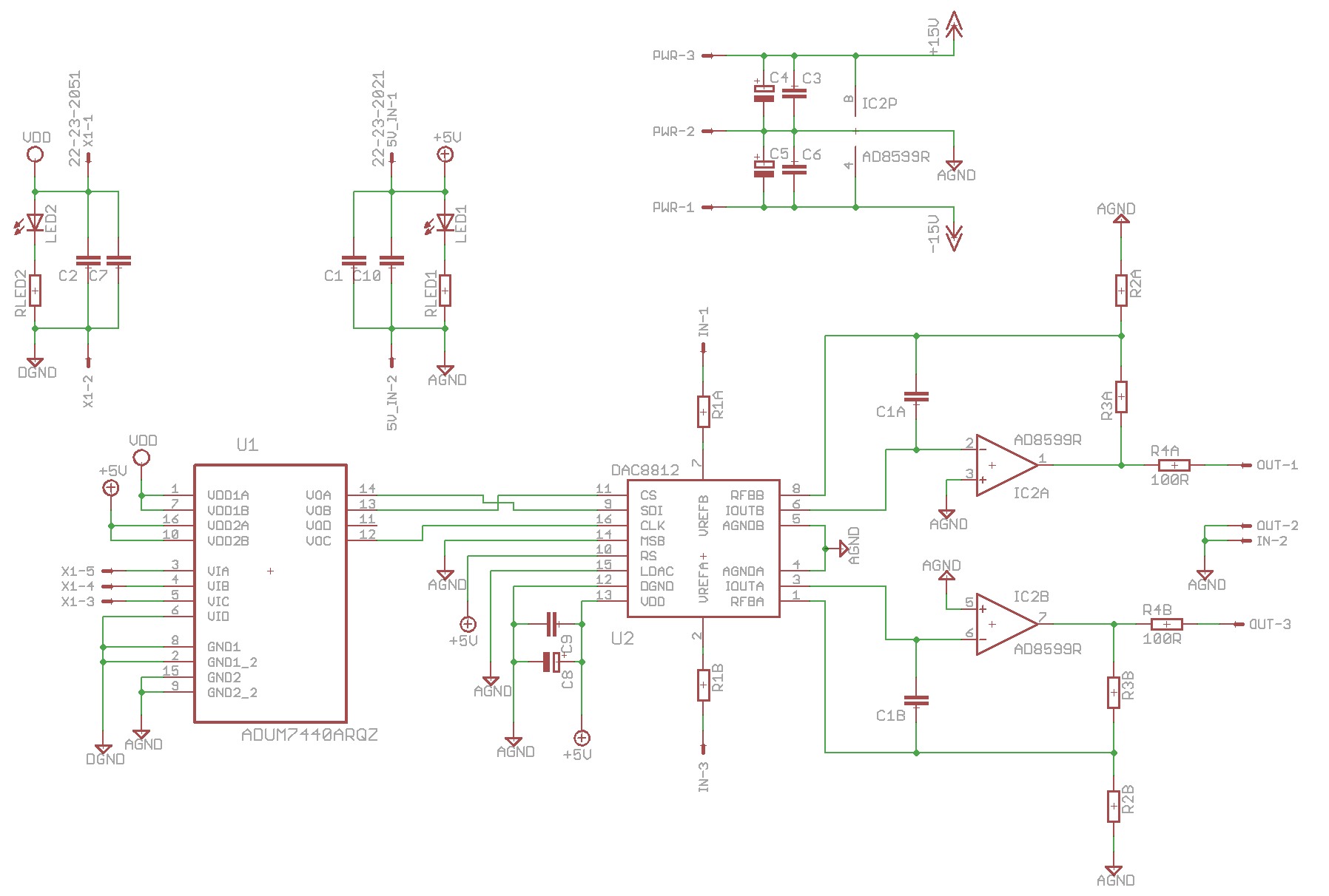
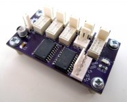
MDAC attenuator
I'll start with the volume control as this is at the core of the design and has the most impact on performance. Because I want to use a remote, the volume control needed to be digitally controlled. The options I could see were
- PGA2310/PGA2320
- A relay based attenuator
- CS3318
- Motor driven pot
- Something else
I'd had problems with many PGA23x0 designs, mainly noise. I'd already made and used a few different relay based attenuators. I tried the CS3318 which was good but I didn't find it very user friendly and fried a couple by simply not powering them down correctly. So I wanted to something else and eventually designed and built an attenuator based on a multiplying R2R DAC.
Although the design uses a DAC IC, the signal is never digital. The signal is converted to current (V to I), then attenuated using the solid state switches and resistors inside the DAC (an R2R ladder). Then converted back to voltage (V to I) using an opamp. It sounds elaborate but it's pretty simple and only uses 2x ICs and 2x caps (no gain) or 2x ICs, 2x caps and 4x resistors (to add gain) in it's simplest form.
All the details about where I got the design and testing can be found in this thread.
Some details about my MDAC attenuator:
- 65536 linear steps (16bit)
- Any gain possible, set by opamp and resistors
- SPI controlled with isolation by using ADuM7440
- Excellent performance (better than PGA2320 in my measurements)
- Can drive headphones
- Can take +/- 10V input
- Compact
- Cost about £35 to build with expensive parts, could be ~£30 with cheaper parts
Eagle schematic/layout and Arduino sketch are attached.
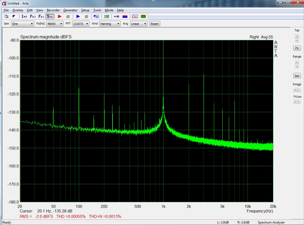
Here is an Arta screenshot. The curve is due to measuring with my E-MU 0404 USB, not the device itself:
I'll start with the volume control as this is at the core of the design and has the most impact on performance. Because I want to use a remote, the volume control needed to be digitally controlled. The options I could see were
- PGA2310/PGA2320
- A relay based attenuator
- CS3318
- Motor driven pot
- Something else
I'd had problems with many PGA23x0 designs, mainly noise. I'd already made and used a few different relay based attenuators. I tried the CS3318 which was good but I didn't find it very user friendly and fried a couple by simply not powering them down correctly. So I wanted to something else and eventually designed and built an attenuator based on a multiplying R2R DAC.
Although the design uses a DAC IC, the signal is never digital. The signal is converted to current (V to I), then attenuated using the solid state switches and resistors inside the DAC (an R2R ladder). Then converted back to voltage (V to I) using an opamp. It sounds elaborate but it's pretty simple and only uses 2x ICs and 2x caps (no gain) or 2x ICs, 2x caps and 4x resistors (to add gain) in it's simplest form.
All the details about where I got the design and testing can be found in this thread.
Some details about my MDAC attenuator:
- 65536 linear steps (16bit)
- Any gain possible, set by opamp and resistors
- SPI controlled with isolation by using ADuM7440
- Excellent performance (better than PGA2320 in my measurements)
- Can drive headphones
- Can take +/- 10V input
- Compact
- Cost about £35 to build with expensive parts, could be ~£30 with cheaper parts
Eagle schematic/layout and Arduino sketch are attached.
Here is an Arta screenshot. The curve is due to measuring with my E-MU 0404 USB, not the device itself:
Attachments
And here's a BOM for the MDAC attenuator:
U1 1827342 ANALOG DEVICES - ADUM7440ARQZ
U2 1390687 TEXAS INSTRUMENTS - DAC8812ICPWG4
IC2 1438872 ANALOG DEVICES - AD8599ARZ Description: IC, OP AMP, DUAL, SMD, SOIC8
C1A, C1B 1759181 MULTICOMP - MCCA000310 Description: CAP, MLCC, C0G/NP0, 2PF, 50V, 0805
R1A/B 1841733 PANASONIC - ERA8AEB910V Description: RESISTOR, 1206, 0.1%, 0.25W, 91R
R2A/B, R4A/B 1841735 PANASONIC - ERA8AEB121V Description: RESISTOR, 1206, 0.1%, 0.25W, 120R
R3A/B 1841744 PANASONIC - ERA8AEB361V Description: RESISTOR, 1206, 0.1%, 0.25W, 360R
C8 2326107 PANASONIC - EEE1AA470WR Description: CAP, ALU ELEC, 47UF, 10V, SMD
X1 1675767 MULTICOMP - MC34655 Description: HEADER, SQUARE PIN, 2.54MM, 5WAY
IN, OUT, PWR 1675765 MULTICOMP - MC34631 Description: HEADER, THT, VERTICAL, 2.54MM, 3WAY
C4, C5 1539485 PANASONIC - EEEFP1E470AP Description: CAP, ALU ELEC, 47UF, 25V, SMD
C1-3, C6-7, C9-10 2320839 MULTICOMP - MC0805B104J500CT Description: CAP, MLCC, X7R, 100NF, 50V, 0805
LED1, LED2 2217976 1206 LED Description: LED, SMD, 1206 BLUE; Bulb Size:-; LED Colour:Blue
RLED1, RLED2 1206 Resistor
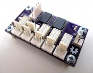
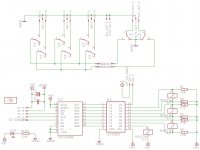
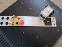
Input selector
For the input selector I wanted to use latching relays so they were not always on and to reduce power consumption. I also figured it would have to be SPI controlled to match the MDAC attenuator otherwise I would have to use two different control protocols which would be a pain in software and with the wiring.
I decided to keep it simple and just use 3x inputs and one mute output. This would allow me to use an 8bit I/O expander IC. Any more inputs and I would need more I/O as each latching relay requires 2x I/O channels.
Features:
- 3x inputs
- Mute
- 1x spare I/O (could be used for a power relay or something later)
- SPI controlled (MCP23S08 IC)
- Compact
- Costs about £19 to build
Pics and Eagle schematic/layout are attached.
Attachments
BOM for the input selector:
IC1 1652419 TEXAS INSTRUMENTS - ULN2803ADW
R1-6 2332121 TE CONNECTIVITY - CRGH1206F47R Description: RESISTOR, POWER, 47R, 0.5W, 1%, 1206;
K1 1175066 TE CONNECTIVITY / AXICOM - IM03TS Description: RELAY, DPDT, 5VDC, 2A, THT; Coil Type: DC Monostable; Contact Configuration😀PDT;
IN, OUT etc 1675765 MULTICOMP - MC34631 Description: HEADER, THT, VERTICAL, 2.54MM, 3WAY;
X1 1675767 MULTICOMP - MC34655 Description: HEADER, SQUARE PIN, 2.54MM, 5WAY;
C2 2326107 PANASONIC - EEE1AA470WR Description: CAP, ALU ELEC, 47UF, 10V, SMD;
C1 1414725 KEMET - C1206C224K5RACTU Description: CAP, MLCC, X7R, 220NF, 50V, 1206;
K2-4 1770588 TE CONNECTIVITY - IM43TS Description: RELAY, DPDT, C/O, 5V, LATCH; Coil Type: DC; Contact Configuration😀PDT;
IC2 1332092 MICROCHIP - MCP23S08-E/SO Description: 8BIT EXPANDER, I/O, SPI I/F, SMD;
LED 2217976 1206 LED Description: LED, SMD, 1206 BLUE; Bulb Size:-; LED Colour:Blue;
RLED 1206 Resistor
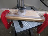
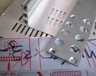
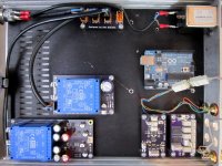
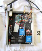
For the case I use the Modu Galaxy as I wanted it to match my Hypex amplifier. They are nice cases, easy to put together and modify. I asked them to send me a non-anodised one as I prefer the look of bare aluminium compared to black anodising. It also makes grounding much easier. I am going to try and make a front panel out of 10mm transparent acrylic but still working out the details.
Attachments
If you are interested, I can post the code that I developed for the UNO R3 to display and change volume level, change input, and rename input (data is stored in EPROM). I started my own project similar to your own, but got sidetracked after working up the GUI. I have not yet written any code to actually do anything, e.g. to change the volume via a digital pot, or switch relays. These are all application specific. I hope to get going again someday since the concept is still something I want to implement.
Here is a thread about it (scroll down to post#19):
http://www.diyaudio.com/forums/mini...-loudspeaker-remote-volume-off-control-2.html
Here is a thread about it (scroll down to post#19):
http://www.diyaudio.com/forums/mini...-loudspeaker-remote-volume-off-control-2.html
Yeah if you could post the code, that would be great. I think I have my code nearly complete but haven't looked at EEPROM yet so would be keen to see how you did that 🙂
I won't post all my code but I will show how I get/store info from/to EEPROM. Each EEPROM position is references by an integer that points to a byte in EEPROM. The byte can be used to store a character or you can convert an integer in the range 0..255 into its byte equivalent and store that.
The EEPROM library that I have is pretty simple - it allows you to put or get one byte at a time. There is 1kB of EEPROM IIRC, which is a good amount, but you have to decide where to store what and how. For instance, here is how I organized my storage:
So, for instance given the above memory structure, here is how I read the data from EEPROM at startup:
The volume scale that I chose uses 0dB for maximum volume and -80dB for minimum volume (or something like that) so you convert the byte stored into an integer and multiplying the result by -1 to get the initial volume setting. The min and max of the volume range are constants set elsewhere in the code.
Below is code that I use to allow the user to specify the text shown for each input. The new input text is then stored into the EEPROM:
You could do fancier things, like having a password requirement for changing input names, etc. For now this covers the basics.
I don't mind if anyone uses or adapts the above code for their purposes.
In my project I have most of the GUI written. I still have to write the parts that actually interface with whatever circuit I use to set the volume, to read a rotary encoder for volume control, and to switch inputs. For now I am happy to share.
-Charlie
The EEPROM library that I have is pretty simple - it allows you to put or get one byte at a time. There is 1kB of EEPROM IIRC, which is a good amount, but you have to decide where to store what and how. For instance, here is how I organized my storage:
Code:
  // MEMORY ORGANIZATION:
  //     WHAT          MEMORY LOCATION
  // TurnOnVolume            0
  // TurnOnInput             1
  // InputNames[i,j]      2+16*i+j; i=input (0-7), j=character pos in name (0-15)
Code:
  TurnOnVolume = -1*int(EEPROM.read(0));
  TurnOnInput = int(EEPROM.read(1));
  for (int i=0; i<8; i++){
    MyString = "";
    for (int j=0; j<16; j++) MyString.concat(char(EEPROM.read(2+i*16+j))); //reads one char from memory and appends to MenuItems
    MyString.trim();
    InputNames[i] = MyString;
  }
  // DONE READING PROGRAM DATA FROM EEPROM.
  // INITIALIZE POWER-UP STATE
  volume = TurnOnVolume;
  CurrentInput = TurnOnInput;
// DONE WITH INITIALIZATIONS.Below is code that I use to allow the user to specify the text shown for each input. The new input text is then stored into the EEPROM:
Code:
void RenameInput() {
  boolean DoneRenaming = false;
  CurrentChar = 65;
  MyString = "       ";
  MyString.concat(char(CurrentChar));
  MyString.concat("          "); //add spaces
  lcd.setCursor(0, 0);
  lcd.print(MyString);
  lcd.setCursor(0, 1);
  lcd.print(InputNames[CurrentInput]);

  while (!DoneRenaming) {
    delay(100);
    uint8_t buttons = lcd.readButtons();

    if (buttons) {
      lcd.setCursor(0, 1);
      if (buttons & BUTTON_UP) {
        CurrentChar+=1;
        if (CurrentChar > 126) CurrentChar = 32;
        lcd.setCursor(0, 0);
        if (CurrentChar==32) MyString = "     SPACE"; else MyString = "       ";
        MyString.concat(char(CurrentChar));
        MyString.concat("  "); //add 2 spaces
        lcd.print(MyString);
      }
      else if (buttons & BUTTON_DOWN) {
        CurrentChar-=1;
        if (CurrentChar < 32) CurrentChar = 126;
        lcd.setCursor(0, 0);
        if (CurrentChar==32) MyString = "     SPACE"; else MyString = "       ";
        MyString.concat(char(CurrentChar));
        MyString.concat("  "); //add 2 spaces
        lcd.print(MyString);
      }
      else if (buttons & BUTTON_LEFT) {
        InputNames[CurrentInput] = InputNames[CurrentInput].substring(0,InputNames[CurrentInput].length() - 1);
        MyString = InputNames[CurrentInput];
        MyString.concat(" "); //add a space
        MyString.toCharArray(MyArray,16);
        lcd.print(MyArray);
        MyString = MyString.substring(0,MyString.length() - 1); //remove the added space
      }
      else if (buttons & BUTTON_RIGHT) {
        MyString = InputNames[CurrentInput];
        if (MyString.length() < MaxInputNameCharacters) {
          InputNames[CurrentInput].concat(char(CurrentChar));
          InputNames[CurrentInput].toCharArray(MyArray,16);
          lcd.print(MyArray);
        }
      }
      else if (buttons & BUTTON_SELECT) {
        char OneChar;
        lcd.setCursor(0, 0);
        lcd.print("SAVING TO EEPROM");
        delay(1500);
        MyString = InputNames[CurrentInput];
        for (int j=0; j<16; j++) {
          if (j < MyString.length() ) OneChar = MyString.charAt(j); else OneChar = char(32);
          EEPROM.write(2+CurrentInput*16+j, OneChar);
        }
        lcd.setCursor(0, 1);
        lcd.print("     DONE !     ");
        delay(1500);
        DoneRenaming = true;
      }
    }
  }
}
You could do fancier things, like having a password requirement for changing input names, etc. For now this covers the basics.
I don't mind if anyone uses or adapts the above code for their purposes.
In my project I have most of the GUI written. I still have to write the parts that actually interface with whatever circuit I use to set the volume, to read a rotary encoder for volume control, and to switch inputs. For now I am happy to share.
-Charlie
Last edited:
Since I didn't do much commenting, let me add some description about what is being done in the Rename Input routine. There are two lines available on the LCD display I am using. The upper line consists of a single centered character (surrounded by spaces). The lower line contains the current text corresponding to the input being edited. The user can:
- use the "up" and "down" button to change the character shown on line 1
- use the "left" button to erase the last character in the text on line 2
- use the "right" button to add the character shown on line 1 to the end of the text on line 2
- use the "select" button to accept the text shown on line 2 as the new input name and store this in the EEPROM
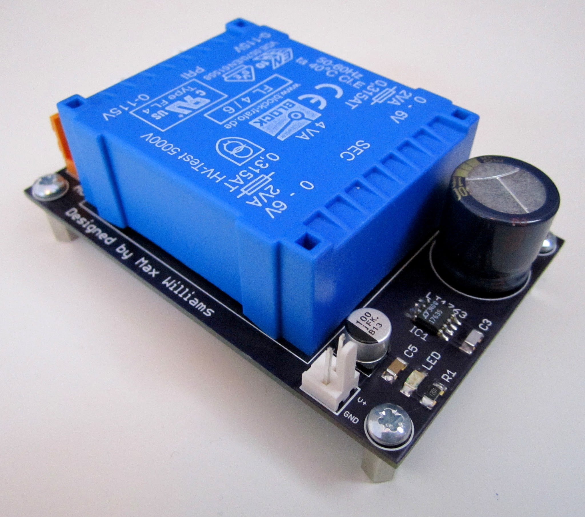
5V Power Supply
I needed a compact 5V power supply to power all the digital items and the DAC in the MDAC attenuator.
It needed to power:
- The Arduino
- MDAC attenuator (Just the DAC IC)
- Input selector
- IR
- Encoder
- LEDs
I wanted something with low noise so that it wouldn't impact the performance of the MDAC attenuator so I designed one with a LT1763 regulator. It's pretty simple, there is a thread about it here with a BoM, layout and schematics.
Current output: 500mA
Cost: ~£25
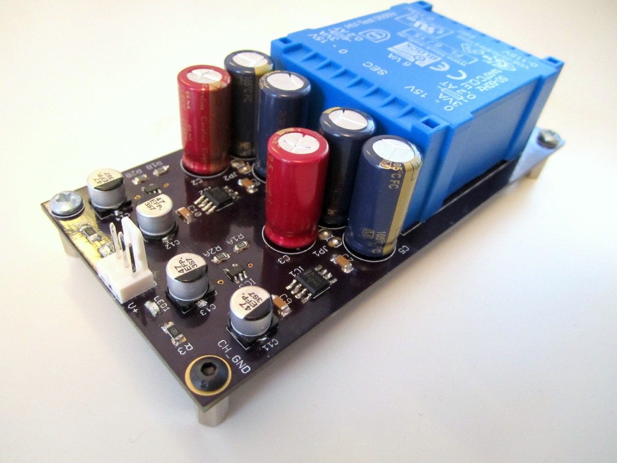
+/- Power Supply
The opamp in the MDAC attenuator needs +/- power. Again, I wanted something low noise and compact so settled on a design that uses 78/79Lxx regulators and then LT1761/LT1964 regulators. There is a thread about it here that inlcudes a BOM, layout and schematics.
Current output: 100mA
Cost: ~£36
The opamp in the MDAC attenuator needs +/- power. Again, I wanted something low noise and compact so settled on a design that uses 78/79Lxx regulators and then LT1761/LT1964 regulators. There is a thread about it here that inlcudes a BOM, layout and schematics.
Current output: 100mA
Cost: ~£36
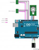
For a microcontroller I'll be using an Arduino Uno R2. They are easy to get, cheap and really easy to program as there is so many examples and libraries already available on the internet. I'll post my full code as it progresses.
Here is version 1.0 of my Arduino code.
Features:
- Control via encoder and Apple remote
- Volume up/down and switch inputs
- Controls both the attenuator and input selector
Still to do:
- Accelerate volume step size when using the remote as it's too slow
- A mute function
- Save volume level to EEPROM
Features:
- Control via encoder and Apple remote
- Volume up/down and switch inputs
- Controls both the attenuator and input selector
Still to do:
- Accelerate volume step size when using the remote as it's too slow
- A mute function
- Save volume level to EEPROM
Attachments
@maxw:
I am about to try and implement a rotary encoder on my own project. Just curious what your experience has been with code, what you used, and if you experienced any problems with contact bounce, etc. or other typical encoder issues.
I am about to try and implement a rotary encoder on my own project. Just curious what your experience has been with code, what you used, and if you experienced any problems with contact bounce, etc. or other typical encoder issues.
I've found the code perfect really, no delay and it changes the volume as fast as I can rotate the encoder.
Low quality encoders do need debouncing sometimes. I've used a load of cheap ones but for this project I'll be using either a 128PPR Bourns EN or a 64PPR Bourns EM14. Once you've used a nice high res encoder the others feel really cheap 🙂 They also don't need debouncing.
Low quality encoders do need debouncing sometimes. I've used a load of cheap ones but for this project I'll be using either a 128PPR Bourns EN or a 64PPR Bourns EM14. Once you've used a nice high res encoder the others feel really cheap 🙂 They also don't need debouncing.
- Home
- Source & Line
- Analog Line Level
- Building a complete Preamp with an Arduino, remote, volume and input control