I've found the code perfect really, no delay and it changes the volume as fast as I can rotate the encoder.
Low quality encoders do need debouncing sometimes. I've used a load of cheap ones but for this project I'll be using either a 128PPR Bourns EN or a 64PPR Bourns EM14. Once you've used a nice high res encoder the others feel really cheapThey also don't need debouncing.
Right, thanks. I was more thinking of exactly WHAT code you used, e.g. did you roll your own or adapt some code from a web page. Also, is this a polling loop that looks for pin changes or an interrupt-on-change, etc.?
I posted the full preamp code above already
No interrupts, I can't remember where I got the code but I would have copied it from somewhere else.
Here are the relevant bits...
No interrupts, I can't remember where I got the code but I would have copied it from somewhere else.
Here are the relevant bits...
Code:
// Encoder stuff
const int encoderPowerPin = 4;
const int encoderGroundPin = 5;
int encoder0PinA = 6;
int encoder0PinB = 7;
int encoder0Pos = 0;
int encoder0PinALast = LOW;
int n = LOW;

void setup() {
  // Set up pins for encoder:
  pinMode (encoder0PinA,INPUT);
  pinMode (encoder0PinB,INPUT);
  pinMode (encoderPowerPin, OUTPUT);
  pinMode (encoderGroundPin, OUTPUT);
  digitalWrite(encoderPowerPin,HIGH);
  digitalWrite(encoderGroundPin,LOW);
}

void loop() {
  // Read encoder
  n = digitalRead(encoder0PinA);
  if ((encoder0PinALast == LOW) && (n == HIGH)) {
    if (digitalRead(encoder0PinB) == LOW) {
      VolumeUp();
    } else {
      VolumeDown();
    }
  }
  encoder0PinALast = n;
}Encoder
You might think that finding a quality high resolution rotary encoder would be simple but it's not! There are tons of low resolutions ones available that are 32 PPR or less but once you've used a nice high res encoder the others feel really cheap.
If you have around 200 volume steps then it would take about 6 rotations to use the full range, which I find annoying. I tried two encoders:
Bourns EN series at 128PPR
Bourns EM14 at 64PPR.
128 PPR is I think this is about as high as you can go and still (just) be able to adjust by a single pulse. Both of these Bourns models are "designed for audio" and the feel of them is really nice compared to the cheap encoders. Also, they don't need debouncing at all in hardware or software.
You might think that finding a quality high resolution rotary encoder would be simple but it's not! There are tons of low resolutions ones available that are 32 PPR or less but once you've used a nice high res encoder the others feel really cheap.
If you have around 200 volume steps then it would take about 6 rotations to use the full range, which I find annoying. I tried two encoders:
Bourns EN series at 128PPR
An externally hosted image should be here but it was not working when we last tested it.
Bourns EM14 at 64PPR.
An externally hosted image should be here but it was not working when we last tested it.
128 PPR is I think this is about as high as you can go and still (just) be able to adjust by a single pulse. Both of these Bourns models are "designed for audio" and the feel of them is really nice compared to the cheap encoders. Also, they don't need debouncing at all in hardware or software.
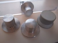
In the end I decided to use the Bourns EN series as it was smoother and higher resolution. The problem with these encoders though, is the shaft size, it's 6.35mm (1/4"). This is a pain because I couldn't find ANY nice knobs with this shaft size, all the nice ones have 6mm holes. I tried drilling the hole in a 6mm knob to 6.35 but it's difficult to get the hole perfectly centred and ended up looking a bit off when the knob was rotated
I tried a shaft extension kit that was compatible with both sizes but the tolerances were too low and again when the knob was rotated it wasn't quite centred.
So I then started to search for something a bit more precise to convert a 6.35mm shaft to a 6mm hole and found these:
I bought one and it works really well but takes up a lot of space in the enclosure.
I tried a shaft extension kit that was compatible with both sizes but the tolerances were too low and again when the knob was rotated it wasn't quite centred.
So I then started to search for something a bit more precise to convert a 6.35mm shaft to a 6mm hole and found these:
An externally hosted image should be here but it was not working when we last tested it.
I bought one and it works really well but takes up a lot of space in the enclosure.
Attachments
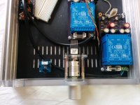
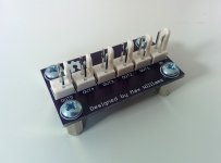
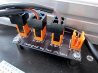
I also designed two simple PCBs for distributing mains and 5V power. It could have easily been done on strip board but I wanted something that looked a bit nicer.
The pin headers and crimp housings on the 5V board are these:
MC34481 - MULTICOMP - CRIMP HOUSING, 2.54MM, 2WAY | Farnell UK
MC34629 - MULTICOMP - HEADER, THT, VERTICAL, 2.54MM | Farnell UK
2218T - MULTICOMP - CONTACT, CRIMP, PLUG, 26-22AWG | Farnell UK
I also used the 3, 4 and 5 pin version on my other designs.
And the 2 pin headers/plugs on the mains board are these:
1716470000 - WEIDMULLER - PLUG, FEMALE, 5.08MM, STRT, 2WAY | Farnell UK
1517260000 - WEIDMULLER - HEADER, THT, VERTICAL, 5.08MM | Farnell UK
Schematics and layout are attached.
Attachments
For the infrared sensor I used this module from Seeedstudio:
Inspired by a lot of the HiFiDuino posts, I decided to use the Apple remote.
My Arduino code uses the IRremote library from here:
https://github.com/shirriff/Arduino-IRremote
There is a more detailed post here about how to use this Arduino library, wiring etc:
Tonight's Arduino Project: An Apple Remote Controlled Buzzer
I've already posted a version of my code that uses this library and it works perfectly. I'll post an updated version of my code soon too.
An externally hosted image should be here but it was not working when we last tested it.
Inspired by a lot of the HiFiDuino posts, I decided to use the Apple remote.
My Arduino code uses the IRremote library from here:
https://github.com/shirriff/Arduino-IRremote
There is a more detailed post here about how to use this Arduino library, wiring etc:
Tonight's Arduino Project: An Apple Remote Controlled Buzzer
I've already posted a version of my code that uses this library and it works perfectly. I'll post an updated version of my code soon too.
Hi Maxw,
I really like your thread, loved to read it and eager for updates.
I'm busy trying something similar to your idea.
Just a small tip, if you'd like to make the holes bigger of the volume knobs use a 1/4" - 6,35 mm reamer.
They're made to make a hole slightly bigger and are very, very accurate.
I prefer to use them in a bench drill (is that the right term?)
So you can really feel what your doing using the Pinole.
Also, put a small cloth or tissue under your know as you're reaming.
And use a bit of wd-40 for lubrication. I'd run the reamer at about 200rpm
This way it'll fit right away on your encoder.
P.s. Make sure that you're using an oversize reamer, H7 or H9 tolerance.
Regards,
Peter
I really like your thread, loved to read it and eager for updates.
I'm busy trying something similar to your idea.
Just a small tip, if you'd like to make the holes bigger of the volume knobs use a 1/4" - 6,35 mm reamer.
Thanks! I've ordered one, I'll post host it goes once I've used it.
I'm a keen follower of this thread too. Beautiful work Max!
Thanks!
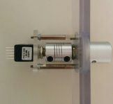
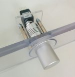
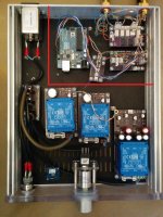
I have made a second separate 5V PSU to use just for the DAC. I'm getting a bit of 50hz interference on measurements so I've bought some aluminium flatbar to use as dividers within the enclosure.
Will update soon...
Will update soon...
Attachments
Hi Max, nice to see a reply!
It's funny, i'm also struggling a bit with 50hz interference. In my case i'm building a preamp and power amp in one.
Right now it's not yet in it's enclosure but i guess it's because i'm not using any filter caps on my psu.
My enclosure will be milled out of billet aluminum. Just one chunk and i'll only remove some pockets for the components and pcb's. They will all be seperated, I hope that'll help.
I'm curious for the result of the aluminum bar.
You're not afraid of interference coming through your plastic front?
Sounds expensive! Post pics when doneMy enclosure will be milled out of billet aluminum. Just one chunk and i'll only remove some pockets for the components and pcb's. They will all be seperated, I hope that'll help.
We'll see. When I've assembled it I'll redo the measurements.I'm curious for the result of the aluminum bar.
You're not afraid of interference coming through your plastic front?
How to use an MDAC attenuator with a balanced signal? Just use 2x MDACs, one per channel. Like you would with a PGA2310 or relay attenuator. Instead of one module attenuating L and R, it would attenuate signal+ and signal-.Very Beautiful work, Max.
Really love the MDAC attenuator. However my system is balance any suggestion how to make it work on balance signal.
Could be! When I install the dividers I'm going to redo all cabling to make it twisted and as short as possible.Max,
the untwisted input pairs could be picking up interference.
Yes it is connected through the bolts of the IEC inlet itself. I've tested it and it makes a good connection throughout the enclosureIs that the Earth Tag on the mains inlet filter that is not connected to Chassis?
Bolt it to the side panel with a short wire.
Are the fixing bolts passing through plastic insulation?
Is any of the aluminium anodised, or liable to corrosion?
Is any of the aluminium anodised, or liable to corrosion?
Bolt it to the side panel with a short wire.
On the outside but the contact is metal to metal where the casing of the IEC socket touches the enclosure. This connection is then pressed together by the machine screws. I think it's solid.Are the fixing bolts passing through plastic insulation?
See my 6th post, I requested a non-anodised case so it conducts well. Aluminium won't corrodeIs any of the aluminium anodised, or liable to corrosion?
Aluminium does corrode.
Anodising is a form of corrosion.
Aluminium oxide is an excellent insulator.
Aluminium oxide is very much harder than aluminium.
Dissimilar metals promote corrosion. The plated surface of the steel IEC socket will react with the aluminium back plate.
The steel screws between the aluminium back plate and the aluminium side panel will increase the risk of corrosion.
A film of corrosion building up on a "assumed" conductive contact can become robust and non conductive.
If that happens you are putting yourself and other operators in danger.
And that is why I said SIDE panel. A different piece of metalwork from the back plate.
Last edited:
A bolted connection that is permanent and corrosion resistant.
Gas tight can achieve the no air/no water contact and that can be OK.
A smear of insulating goop (vaseline) helps, as does serrated washers.
The DESIGN of the mechanical parts is just as involved as the DESIGN of the amplifier parts.
You need to research both when you DIY.
Ignorance is no defense when something goes wrong.
BTW,
copper oxide is also very robust. Corrosion here is to be considered where copper is joined to other metals.
Tinned copper may be frowned upon, but it does offer very good corrosion protection of the copper (gastight). The solder corrosion is very soft and not robust.
Last edited:
- Home
- Source & Line
- Analog Line Level
- Building a complete Preamp with an Arduino, remote, volume and input control