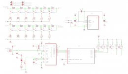
64 step relay attenuator using an ADC0804 8-bit ADC.
I am not using the 2 lowest lsb's.
The biggest problem when using something like an ADC0804 together with relays for attenuation purposes is that you can get situations where one relay releases(breaks) before other relays has time to operate(make). This is especially a problem with 100000>011111 transitions where you risk having no attenuation if the first relay turns off before the 5 other relays activates.
The solution is to implement a make before break action. This is usually done by having a microcontroller control all the relays which makes it easy to insert delays that give you the desired make before break action.
However, what if we could use the characteristics of the relays to get the same desired make before break action?
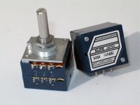
Looking at the datasheet for the excellent low signal relay Omron G6K-2P-Y it is shown that operate and release times are identical at 3mS MAX with 1.4mS as a typical value. Bummer. However, when designing with relays it is good practice to include a flyback diode to protect the BJT or FET used for switching on/off the relay. The downside to this is that you get longer release times, usually on the order of 5+ mS.
In this case the longer release times should in theory give you enough time delay between the making and breaking of the relays to avoid the no attenuation situation.
This is what I have tried to implement here.
The pot should be wired so that when it is turned fully ccw, you get the full voltage to the ADC which makes all the relays go on and giving you full attenuation. Now as you turn the relay the voltage drops, turning on/off relays as you go. Since we have slowed down the release time due to using a flyback diode all the relays should in theory ensure you get a make before break action at all times.
Does the theory hold true in real life? I do not really know but I have convinced myself that it would work just fine.
I am not using the 2 lowest lsb's.
The biggest problem when using something like an ADC0804 together with relays for attenuation purposes is that you can get situations where one relay releases(breaks) before other relays has time to operate(make). This is especially a problem with 100000>011111 transitions where you risk having no attenuation if the first relay turns off before the 5 other relays activates.
The solution is to implement a make before break action. This is usually done by having a microcontroller control all the relays which makes it easy to insert delays that give you the desired make before break action.
However, what if we could use the characteristics of the relays to get the same desired make before break action?
Looking at the datasheet for the excellent low signal relay Omron G6K-2P-Y it is shown that operate and release times are identical at 3mS MAX with 1.4mS as a typical value. Bummer. However, when designing with relays it is good practice to include a flyback diode to protect the BJT or FET used for switching on/off the relay. The downside to this is that you get longer release times, usually on the order of 5+ mS.
In this case the longer release times should in theory give you enough time delay between the making and breaking of the relays to avoid the no attenuation situation.
This is what I have tried to implement here.
The pot should be wired so that when it is turned fully ccw, you get the full voltage to the ADC which makes all the relays go on and giving you full attenuation. Now as you turn the relay the voltage drops, turning on/off relays as you go. Since we have slowed down the release time due to using a flyback diode all the relays should in theory ensure you get a make before break action at all times.
Does the theory hold true in real life? I do not really know but I have convinced myself that it would work just fine.
Attachments
Last edited:
If you were to use say a 6V relay with a resistor to the +12V rail, and placed a cap from the junction to the negative rail, then on switch on the relay would see 12V dropping to 6V once the cap discharged.
Where to place the catch diode takes thinking about, and using a low Vf diode will also delay the turn off.
This is a fairly standard trick in TR switches in HF radios where getting the antenna transfer relay over quickly improves the operational experience (especially when sending morse).
73 Dan.
Where to place the catch diode takes thinking about, and using a low Vf diode will also delay the turn off.
This is a fairly standard trick in TR switches in HF radios where getting the antenna transfer relay over quickly improves the operational experience (especially when sending morse).
73 Dan.
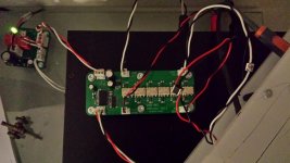
Sorry for the crappy picture.
It is alive and it works!
It has 64, 1.3 dB steps, min volume is essentially the same as mute.
I do have some "popping" sounds when turning the volume, from min volume to max volume I get about 2-3 "pops" and the same when turning down the volume.
Also, it is possbile to set the pot so that the realys goes into full chatter mode, not a good thing but it happens rarely.
The sound? Hard to say what the difference is between this and a cheap Alps RK27. However, what the relay attenuator definately does better is channel balance, it is perfect all the way down to min volume.")
Also it does sound a little bit clearer and more detailed than before, but that could just as well be my mind playing a few tricks on me.
Could I live with the few "pops" and the risk of the relays going into full chatter mode? Hard to say, I definately have to play around with it some more.
It is alive and it works!
It has 64, 1.3 dB steps, min volume is essentially the same as mute.
I do have some "popping" sounds when turning the volume, from min volume to max volume I get about 2-3 "pops" and the same when turning down the volume.
Also, it is possbile to set the pot so that the realys goes into full chatter mode, not a good thing but it happens rarely.
The sound? Hard to say what the difference is between this and a cheap Alps RK27. However, what the relay attenuator definately does better is channel balance, it is perfect all the way down to min volume.
Also it does sound a little bit clearer and more detailed than before, but that could just as well be my mind playing a few tricks on me.
Could I live with the few "pops" and the risk of the relays going into full chatter mode? Hard to say, I definately have to play around with it some more.
Attachments
Last edited:
Also it is possible to set the pot so that the relays go into full chatter mode, not a good thing but it happens rarely.
Hi, why is that and can it be solved ? Software thing ? Better still include the flyback diodes although IC2 is supposed to be protected or at least add the pads.
Just an idea: this device will probably be mounted on the internal back side of the preamp/amp ? Why not include the potentiometer on the board and operate it with an extension rod ? When the MKDSN connector is also added the device will be more versatile. I get carried away but just 4 relays added would make it a complete input switcher and volume control board (totally passive)....
Also please consider the use of an RC filter at the input to keep our friends HF and RF outside.
Do I hear Group Buy ? I am sure I did !
Last edited:
Hi, why is that and can it be solved ? Software thing ?
Do I hear Group Buy ? I am sure I did !
There is no software, the ADC0804 is n 8-bit uP compatible A/D Converter, there is no software needed.
You basically just have a pot with the same voltage on it as the ADC0804 is supplied with and use that to vary the voltage the ADC0804 sees on its inputs and it corverts it into bits, which controls the relays.
The chatter most likely happens when you turn the pot and end up with a voltage that is just between 2 different bits and that makes the ADC0804 go crazy. I could probably add a decoupling cap to the input pin and see if that makes any difference.
The 2-3 "pops" I get is most likely something I will have to live with, but who knows, I might find a solution at a later date.
Group buy? I don't know, almost everything is SMD and people would have to live with the occasional "pop" and relay chatter.
Last edited:
Better still include the flyback diodes although IC2 is supposed to be protected or at least add the pads.
Also please consider the use of an RC filter at the input to keep our friends HF and RF outside.
IC2 has flyback diodes included in the IC, no external flyback diodes required.
There will be an RC filter on a separate Input Gain board, that will be connected before the Attenuator.
Basically my plan is this :
Input Gain Board(variable between 2 gain settings, most likely 1x(0dB) and 2x(6dB)) > Attenuator > Output gain boards(Fixed 2x(6dB) gain, output buffer, BUF634).
Last edited:
There is no software, the ADC0804 is n 8-bit uP compatible A/D Converter, there is no software needed.
You basically just have a pot with the same voltage on it as the ADC0804 is supplied with and use that to vary the voltage the ADC0804 sees on its inputs and it corverts it into bits, which controls the relays.
The chatter most likely happens when you turn the pot and end up with a voltage that is just between 2 different bits and that makes the ADC0804 go crazy. I could probably add a decoupling cap to the input pin and see if that makes any difference.
The 2-3 "pops" I get is most likely something I will have to live with, but who knows, I might find a solution at a later date.
Group buy? I don't know, almost everything is SMD and people would have to live with the occasional "pop" and relay chatter.
Got that, was reacting too fast and I reread. So it could be "in between" bits or maybe the potentiometer that varies value in a certain angle ? What if you use a stereo potentiometer with both channels in parallel just to test ? Can hysteresis be added ? Just asking as I am not familiar with this solution> Mostly I see the PIC buzzword when reading about relay driven volume control...
IMO the device asks for a GND reference resistor as the series resistors always are in series but their value can change. They are however always connected. The shunt resistor for the chosen volume level can momentarily loose its connection to GND as the relay is switching so GND reference is lost for a short while. This would cause plops either from loosing GND or from an unexpected change in volume..... So 1 resistor that always makes GND reference after R11/R12 could be enough if GND reference is what's needed. Or it is simply the lack of timing possibilities for "make before break" which would aks for a PIC. Just thinking out loud.
- A shunt resistor from the middle pin of the potentiometer to GND to have a resistance value and no open input of the ADC if it scratches or has conduction problems ?
- From the middle pin of the potentiometer an RC filter to the input pin of the ADC ?
And RC filters at both boards at different - 3 dB values wouldn't hurt.
Last edited:
Got that, was reacting too fast and i reread. So it could be "in between" bits or maybe the potentiometer that varies value in a certain angle ? What if you use a stereo potentiometer with both channels in parallel just to test ? Can hysteresis be added ? Just asking as I am not familiar with this solution> Mostly I see the PIC buzzword when reading about relay driven volume control...
IMO the device asks for a GND reference resistor as the series resistors always are in series but their value can change. They are however always connected. The shunt resistor can momentarily loose their connection to GND as the relay is switching so GND reference is lost for a short while. This would cause plops either from loosing GND or from an unexpected change in volume..... So 1 resistor of 100 kOhm after R11/R12 could be enough if GND reference is what's needed. Just trying to help.
Hysteresis? Well, It could probably be added but that would increase the complexity and it would be easier to do everything in software instead and software, that is not something I do.
There is already an resistor after R11/12, it is in the amp the attenuator is connected to, it is 21K5(it should ideally be 10K, but for testing purposes 21K5 will do).
Or it is simply the lack of timing possibilities for "make before break" which would aks for a PIC. Just thinking out loud.
Exactly, that is most likely the issue, I hoped my implementation of it would work around that without the need for a PIC or similar processor
It does seems to have minimized the issue somewhat since I only get the aforementioned 2-3 "pops" in a full turn of the pot.
Hysteresis? Well, It could probably be added but that would increase the complexity and it would be easier to do everything in software instead and software, that is not something I do.
There is already an resistor after R11/12, it is in the amp the attenuator is connected to, it is 21K5(it should ideally be 10K, but for testing purposes 21K5 will do).
That should suffice if the amp has no input cap before it
That should suffice if the amp has no input cap before it
It has not, I built it myself.
Another option for the "pops" that I have not mentioned yet could be what one could call "momentary DC", basically, when we switch relays on/off, it could happen at the peak of the AC cycle, which would result in a situation where you go from no volume to some peak value just for a moment, that would also create a "pop". The only way to insure that does not happen is zero cross detection, which means that you only switch volume levels when the signal crosses zero(GND). This is done in volume control ICs like PGA2311. However, this is not pssobile with relay based attenuator since their on/off switch characteristics are : 1) Too unpredictable, 2) Relays are too slow.
This is something that ALL relay based attenuators have to deal with, even those that use a PIC or similar micro processor. There just isn't any good way of avoiding that potential "momentary DC" "pop".
This is something that ALL relay based attenuators have to deal with, even those that use a PIC or similar micro processor. There just isn't any good way of avoiding that potential "momentary DC" "pop".
Last edited:
Mmmm, I know a solution for that that's cheap and reliable
I know, I have always used Alps RK27, it is a nice cheap pot that just works.
But it is always fun to try out new things.
Ha ha stuff that just works and keeps working. What more would one want ? Possibly age matters as I real start to appreciate simple reliable stuff more and more. Just take espresso machines for instance. After having several of these devices that have one thing in common (they do breakdown when you need a good coffee) I went back to the Braun that always works ...
Attachments

Last edited:
Did some testing today.
I sent 5VDC through the attenuator and looked at the output with my oscilloscope and their indeed are short switching glitches which explains why I get a few "pops" when adjusting the volume.
The diodes included in the ULN2004 relay driver have a typical vF of 1.7V@350mA, more than regulaor diodes and this should give me a faster release time than if I had used regular diodes.
So I removed the ULN2004 common diode connection from +12V and let it float.
Instead I added external "normal" diodes with a vF of 0.850V@350mA. Again looking at the switching glitches on my scope this does seem to increase the release time of the relays since the switching glitches have been reduced in time.
Listening to the attenuator in my system with audio playing and adjusting the volume I still get "pops", which is as expected, however it does sound like what I saw on my scope carreid over to a real world usage scenario, the "pops" aren't as annoying as before. Great.
On their way to me is a bunch of Schottky diodes with a vF of 0.38V@350mA, which hopefully should increase the relay release times even more and result in a further reduction of the "pops" I get.
If that works out, bringing me almost close to home, I might implement what was suggested in post #3 and see if that could make me reach my goal of "pop" free operation.
One last thing, I got a solution to the relay chatter due to possible instability of the first LSB. It is nothing that has not been done before, I found the solution looking through old threads here on DiyA. But it will definately work very well, removing all instability.
I sent 5VDC through the attenuator and looked at the output with my oscilloscope and their indeed are short switching glitches which explains why I get a few "pops" when adjusting the volume.
The diodes included in the ULN2004 relay driver have a typical vF of 1.7V@350mA, more than regulaor diodes and this should give me a faster release time than if I had used regular diodes.
So I removed the ULN2004 common diode connection from +12V and let it float.
Instead I added external "normal" diodes with a vF of 0.850V@350mA. Again looking at the switching glitches on my scope this does seem to increase the release time of the relays since the switching glitches have been reduced in time.
Listening to the attenuator in my system with audio playing and adjusting the volume I still get "pops", which is as expected, however it does sound like what I saw on my scope carreid over to a real world usage scenario, the "pops" aren't as annoying as before. Great.
On their way to me is a bunch of Schottky diodes with a vF of 0.38V@350mA, which hopefully should increase the relay release times even more and result in a further reduction of the "pops" I get.
If that works out, bringing me almost close to home, I might implement what was suggested in post #3 and see if that could make me reach my goal of "pop" free operation.
One last thing, I got a solution to the relay chatter due to possible instability of the first LSB. It is nothing that has not been done before, I found the solution looking through old threads here on DiyA.
But it will definately work very well, removing all instability.
Last edited:
The bad news is that schottky diodes made absoluely no difference, still get "pops".
The good news is that the "anti chatter" circuit works perfectly, the attenuator is now perfectly stable.
So I now have 3 options, 1) Live with the few "pops" I get when adjusting the volume, 2) Try to find another solution that will fix the "pops", 3) End the project and go back to the good old Alps RK27, performance is more or less good enough, it just works.
Last edited:
- Home
- Source & Line
- Analog Line Level
- ADC0804 Relay Attenuator