With LME49720 i use 0,1uf and 10uf cap see datasheet...page 37 http://www.ti.com/lit/ds/symlink/lme49720.pdf100nF Monolithic 50V X7R. IIRC all the capacitors on the P88 PCB went across the rails and not to ground. I can't remember the section with the 2 electrolytics as I only have the first stage PCB left.
Attachments
PSU for P88 and P06So here's my version of a 317/337 power supply. Very much inspired by the rod elliott / doug self / muffsy designs of course. i'm very new to pcb design so any feedback would be welcome.
Attachments
Sadface - you mentioned going for a dual LT1086 design for lower noise. What kind of noise figures are you expecting?
I don't have any equipment to measure other than my ears.
I'm working off the idea that I may as well start with the best theoretical base and then try to build something that approximates best practice in implementation.
I had developed a version 1 of a bipolar LT1086 board.

But then I had a read of the denoiser thread and decided I might design a board that essentially grafts a denoiser onto a ESP P05.
Here's my latest version of the preamp pcb also.

Last edited:
If you incorporate Elvee's denoiser (a GREAT idea!), then you MUST base it on LT317/337s rather than the LM78/79xxs depicted in Rod's P05. If you design a PCB doing this, count me in---I'll spring for a few. I think Elvee's idea is the easiest, most economical, and best performing concept for a regulator I've seen.But then I had a read of the denoiser thread and decided I might design a board that essentially grafts a denoiser onto a ESP P05.
If you incorporate Elvee's denoiser (a GREAT idea!), then you MUST base it on LT317/337s rather than the LM78/79xxs depicted in Rod's P05. If you design a PCB doing this, count me in---I'll spring for a few. I think Elvee's idea is the easiest, most economical, and best performing concept for a regulator I've seen.
That is my conclusion as well; simple, cheap and with a theoretical noise floor so low that as long as I implement a half decent board design, the community should have something high performance, modular and adaptable to various voltages.
My idea would be to release the gerber files so that all and sundry can order their own. JLCpcb is all of $2 for 5 boards + shipping and that would save me the tying up my own money in a large order of boards and the bother of shipping them out everywhere.
Last edited:
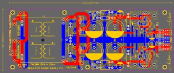
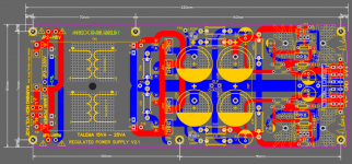
So here's my version of a 317/337 power supply. Very much inspired by the rod elliott / doug self / muffsy designs of course. i'm very new to pcb design so any feedback would be welcome.
I wouldn't recommend transformer on the regulator PCB. Ideally, transformer should be as far as possible from any active circuitry, including regulator circuitry. The best place for the transformer would be outside of enclosure, or inside enclosure as far as possible from all active circuitry.
You should advise xrk971, they have 2 transformers on the same board for Yarra PreampI wouldn't recommend transformer on the regulator PCB. Ideally, transformer should be as far as possible from any active circuitry, including regulator circuitry. The best place for the transformer would be outside of enclosure, or inside enclosure as far as possible from all active circuitry.
Attachments
PSU for P88 and P06
Hello Hicoco,
Nice professional PCB.
In my opinion, trafo on PCB shouldnt matter much atleast in terms of audibility.
Also, since you have dual seconday trafo, better to make dual bridge rectifier section.
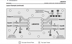
However with lm317/337, all its grounds should be connected to the out put for lowest noise.
look at the example here.
Juma's Head Amp
regards
Prasi
Bonjour Prasi,Hello Hicoco,
Nice professional PCB.
In my opinion, trafo on PCB shouldnt matter much atleast in terms of audibility.
Also, since you have dual seconday trafo, better to make dual bridge rectifier section.
However with lm317/337, all its grounds should be connected to the out put for lowest noise.
look at the example here.
Juma's Head Amp
regards
Prasi
Thanks, Yes you are right, i changed the design for grounds connected to the output.
Attachments
Trafo on the PCB is a disaster. Electromagnetic field of the trafo acts as source of interference. Unlike RF interference it is impossible to shield circuit effectively against EM interference. Especially in high gain circuits, like RIAA and other preamplifier circuits, this interference is amplified, the circuit treats this interference as useful signal. Regulator circuit is DC amplifier circuit and all this interference is amplified. What's worse, this interference can not be removed in any way. Even using Mu metal shielding for the transformer is not good enough. There is no point in building complicated low noise regulator and to put transformer one inch away from it. Total nonsense!
The only reason why we build power amplifier in separate enclosure is to be able to keep preamplifier enclosure as far as possible from power amplifier transformer which has very powerful EM field. There is no point in using separate enclosures if you keep preamplifier directly on the power amplifier. Preamplifer should be connected with power amp using decent length of coax cable. They should be separated at least half a meter.
The only reason why we build power amplifier in separate enclosure is to be able to keep preamplifier enclosure as far as possible from power amplifier transformer which has very powerful EM field. There is no point in using separate enclosures if you keep preamplifier directly on the power amplifier. Preamplifer should be connected with power amp using decent length of coax cable. They should be separated at least half a meter.
So I'm working on the PCBs for my preamp an the grounding scheme is still a bit of a misery to me. Attached a draft of how I think it could work:
All Input GND tied together at input and only one connection to the RIAA pre and line stage. Only one connection from line stage OUT to Output connectors. Turntable GND is tied together at input with all other inputs. Virtual GND of the PSU is routed with the DC power +/-. See attached image. Does that make sense at all?

All Input GND tied together at input and only one connection to the RIAA pre and line stage. Only one connection from line stage OUT to Output connectors. Turntable GND is tied together at input with all other inputs. Virtual GND of the PSU is routed with the DC power +/-. See attached image. Does that make sense at all?
Last edited:
Can't hide my excitement (and my phone is very old, hence the bad picture quality).
I just received the first ever shipment of PCBs I designed myself. They look fantastic and jlcpcb was super fast.
- 15v dual suppply
- p06 ispired phono pre with switchable gain and impedance
- p88 inspired line stage with switchable inputs and gain
...just in time for the holiday season. Let's hope the layout is correct
They look even better in reality. I'm really quite fascinated by the quality that jlcpcb provides.
And thanks again for your help, Oleg! Your support and advice was incredibly valuable. I'll see if the boards work in the next couple of days. In case you're interested I'd gladly offer you a set. It should make for a nice little preamp with phono stage.
And thanks again for your help, Oleg! Your support and advice was incredibly valuable. I'll see if the boards work in the next couple of days. In case you're interested I'd gladly offer you a set. It should make for a nice little preamp with phono stage.
Nice work Mixi, Those look very professional.
I've also been quite impressed with JLC. Between JLC and DHL they managed to deliver in 4 business days to Auckland NZ.
The quality of the boards is great. I went with black and it came out fantastic.
Here is some photos of my mono preamp boards.


Here's my denoiser power supply board half completed.

I've also been quite impressed with JLC. Between JLC and DHL they managed to deliver in 4 business days to Auckland NZ.
The quality of the boards is great. I went with black and it came out fantastic.
Here is some photos of my mono preamp boards.
Here's my denoiser power supply board half completed.
G'day Guys,
Here's my latest development in this series.


I have removed the coupling caps as there are not needed with the LME49720 due to its fancy DC blocking circuitry.
I added a footprint for an RC filter to the input. With my previous version, I was getting some harshness in the treble which was eliminated by tacking a 330pF ceramic cap on the underside to make an RC filter.
I have separated the power ground from the signal ground by running some extra traces on the top side for the power ground. The star is located at the PSU ground.
Lastly I have added footprints underneath the opamp to accommodate two 5mA constant current diodes running from the power supply pins to the output pins on the chips. It was suggested to me that by doing so I can force the output stages to run in Class A up to 7Vrms.
Any critiques?
Here's my latest development in this series.
I have removed the coupling caps as there are not needed with the LME49720 due to its fancy DC blocking circuitry.
I added a footprint for an RC filter to the input. With my previous version, I was getting some harshness in the treble which was eliminated by tacking a 330pF ceramic cap on the underside to make an RC filter.
I have separated the power ground from the signal ground by running some extra traces on the top side for the power ground. The star is located at the PSU ground.
Lastly I have added footprints underneath the opamp to accommodate two 5mA constant current diodes running from the power supply pins to the output pins on the chips. It was suggested to me that by doing so I can force the output stages to run in Class A up to 7Vrms.
Any critiques?
G'day Chaps,
My class A version passed initial testing today.
No sparks or magic smoke. No strange noises, hiss or hum.
Just music.

E562 constant current diodes mounted on the underside of the board directly below the IC.

The new boards beside my last version.

As implemented with a denoiser PSU.
Tomorrow I will plug it into my main rig for some proper testing at volume!
My class A version passed initial testing today.
No sparks or magic smoke. No strange noises, hiss or hum.
Just music.
E562 constant current diodes mounted on the underside of the board directly below the IC.
The new boards beside my last version.
As implemented with a denoiser PSU.
Tomorrow I will plug it into my main rig for some proper testing at volume!
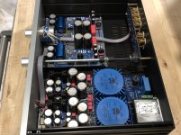
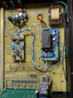
A while back I purchased a dead Conrad Johnson PF-R preamp on ebay. The audio power supply was dead, the transformer was bad, and tracks on the PC board in the power supply area were damaged. Conrad Johnson was no help with schematics or parts, so, I took another approach. I stripped the audio section and installed a ESP 88 preamp from Rod Elliott, and I used power supply module from Neurochrome. I omitted the volume and balance functions of ESP 88 relying instead on the PF-R volume circuitry, which is prior to the input of the ESP 88 board. I'm currently using the OPA 2134 op amps. While I ws at it, I updated the caps on the input/output section of the PF-R. The PF-R functions normally from a user perspective and sounds surprisingly good. I'm now curious about what the ESP 88 can sound like with high end capacitors on the front and back ends of the board. Does anyone have recommendations in this regard?
Attachments
- Home
- Source & Line
- Analog Line Level
- Rod Elliot Project 88 question