To calculate the zobel network what's the correct value: nominal impedance or DC resistance (Re)?
Re
But, I can usually do a little better using XSim and tweaking it. 🙂
Also, bumping the values of the Zobel you can sometimes nudge the driver phase a little, helping with driver matching.
So use the calculators only as a starting point.
Best,
E
But, I can usually do a little better using XSim and tweaking it. 🙂
Also, bumping the values of the Zobel you can sometimes nudge the driver phase a little, helping with driver matching.
So use the calculators only as a starting point.
Best,
E
Well, you need to include both Re AND LE in calculations. Here is one online calculator:
ERSE - Crossover Calculator - Zobel Circuit
ERSE - Crossover Calculator - Zobel Circuit
It is also very easy to calculate by hand or with a spreadsheet. I believe it is:
R = Re
C = L/(R*R)
When using an online calculator, or software, be careful with the units! mH and H are not the same. 🙂 Same with uF vs. F
R = Re
C = L/(R*R)
When using an online calculator, or software, be careful with the units! mH and H are not the same. 🙂 Same with uF vs. F
Speaker Zobel / Impedance Equalization Network Circuit Calculator
but I use this, Felipe
Dayton Audio Dayton Audio Test System | DATS
.... or the poor man jig.
https://www.roomeqwizard.com/help/help_en-GB/html/impedancemeasurement.html
Cheers
but I use this, Felipe
Dayton Audio Dayton Audio Test System | DATS
.... or the poor man jig.
https://www.roomeqwizard.com/help/help_en-GB/html/impedancemeasurement.html
Cheers
Ah, the inevitable re-appearance of that piece of nonsense formula for speaker impedance correction, falsely attributed to Zobel. The correct method to obtain a flat impedance with minimum phase i.e. the speaker will look like a resistance in the crossover frequency range is to use Boucherot's method for power factor correction. This involves finding the impedance and phase of the speaker at the crossover frequency and solving for R=cos theta.Z and for XL= sin theta.Z From this information vector formula methods are used to resolve the distribution of current in the correction circuit to find the values for C and R. The Smith & Larson Woofer Tester will do all this for you, if you are not familiar with the maths involved.
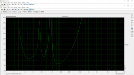
Without zobel
With zobel as per calculator 12.2uF + 7 ohms (using Re)
With zobel 9uF + 8,2 ohms (using nominal driver impedance not Re)
An externally hosted image should be here but it was not working when we last tested it.
With zobel as per calculator 12.2uF + 7 ohms (using Re)
An externally hosted image should be here but it was not working when we last tested it.
With zobel 9uF + 8,2 ohms (using nominal driver impedance not Re)
An externally hosted image should be here but it was not working when we last tested it.
Last edited:
You need prolly 5-10 times the Capacitor on that one.
Lets say it is 2.5mH inductance and 5.6ohm
0.0025/5.6^2=80uF capacitance
Lets say it is 2.5mH inductance and 5.6ohm
0.0025/5.6^2=80uF capacitance
Last edited:
Because 12uF has a reactive impedance of ~26ohms at 500Hz, just like what your plot is showing.
You need a capacitor that has a low impedance at the higher frequency so that the source sees the added R as a load in parallel to the voice coil.
Effective impedance = sqrt (26.5^2 + 7^2) =~27ohms.
You need a capacitor that has a low impedance at the higher frequency so that the source sees the added R as a load in parallel to the voice coil.
Effective impedance = sqrt (26.5^2 + 7^2) =~27ohms.
Last edited:
You need prolly 5-10 times the Capacitor on that one.
Lets say it is 2.5mH inductance and 5.6ohm
0.0025/5.6^2=80uF capacitance
Where do you take 2.5mH?
Thanks Andrew now I understand how it's work.
Because 12uF has a reactive impedance of ~26ohms at 500Hz, just like what your plot is showing. please show me the maths to calculate by myself
You need a capacitor that has a low impedance at the higher frequency so that the source sees the added R as a load in parallel to the voice coil.
Effective impedance = sqrt (26.5^2 + 7^2) =~27ohms. what's 26.5 & 7?

Because 12uF has a reactive impedance of ~26ohms at 500Hz, just like what your plot is showing.
You need a capacitor that has a low impedance at the higher frequency so that the source sees the added R as a load in parallel to the voice coil.
Effective impedance = sqrt (26.5^2 + 7^2) =~27ohms.
Frequency F0 =1/{2PiXcC} for capacitor and F0 = XL/{2PiL}Thanks Andrew now I understand how it's work.
XL= 2*Pi*F0*L
This is 90degrees phase difference to the resistor's impedance.
You add these two 90degrees phase difference impedances using the sqrt of squares rule
Effective impedance = Sqrt( XL^2 + R^2)
Xl is the inductor impedance.
As we would describe Xc as the capacitor impedance.
If you have an RC filter you choose the R and C values and find the F0 (=F-3dB) frequency
Same for an LR filter.
As we would describe Xc as the capacitor impedance.
If you have an RC filter you choose the R and C values and find the F0 (=F-3dB) frequency
Same for an LR filter.
Hi merlin el mago,
Before you run an impedance test in Limp, make sure you run a calibration test via the CAL button.
After that, measure the impedance of a resistor (for example 8.2 ohms metal film or metal oxide). If the response (in ohms and phase) is nice and flat, you can then be assured that your loudspeaker impedance measurements will be accurate.
If the response in ohms or phase are not flat, you may be able to correct this via the cable compensation button next to the CAL button.
Hope this helps.🙂
Peter
- Status
- Not open for further replies.
- Home
- Loudspeakers
- Multi-Way
- Zobel