Hi,
(sorry for my modest english!)
Diyaudio is one of my favorite source of "hobby". First, thanks to everybody here for animating such a source of information. I'm just a noob, but i like a lot to try linking things i read to try to understand better. Reading some page of myrev c amp, and other thread, about zobel, phase and damping, i came to a question.
Damping can be not linear in frequency range. It seems that if damping is not constant, phase neither. Am i right ? But damping, is about speaker resistance too (and impedance?). So zobel reducing impedance at high frequency, should make damping more constant, and so should help to get a better phase response ?
Does it make sense ?
So zobel should help high inductance subwoofer to be in phase with mid/high, not only when using passive crossover, but with active crossover too ?
In My "audiophile" LM3886 approach :
Thanks,
Damien
(sorry for my modest english!)
Diyaudio is one of my favorite source of "hobby". First, thanks to everybody here for animating such a source of information. I'm just a noob, but i like a lot to try linking things i read to try to understand better. Reading some page of myrev c amp, and other thread, about zobel, phase and damping, i came to a question.
Damping can be not linear in frequency range. It seems that if damping is not constant, phase neither. Am i right ? But damping, is about speaker resistance too (and impedance?). So zobel reducing impedance at high frequency, should make damping more constant, and so should help to get a better phase response ?
Does it make sense ?
So zobel should help high inductance subwoofer to be in phase with mid/high, not only when using passive crossover, but with active crossover too ?
In My "audiophile" LM3886 approach :
More it is constant the damping and ( over all ) more is constant the phase to all the frequencies, more ( in accordance with Graham and in accordance with me ) gets a sound " clear and equlibrate ".
Thanks,
Damien
The Zobel is a high frequency load for the amplifier.
It has nothing to do with audio loads provided by the speaker.
The speaker can be disconnected and the Zobel still provides a high frequency load for the amplifier.
Many amplifiers change gain when the load is changed.
If the amplifier gain changes a lot at high frequency when the load is infinite, then that can cause instability.
The Zobel is there so that the amplifier does not see infinity as a load at high frequencies, even when the speaker is away in another room.
Forget about the Zobel affecting the audio phase.
The Zobel is a load that operates above the audio frequencies.
Take a standard pair of Zobel values, say 100nF and 10r.
The F-3dB frequency of this pair is 159kHz
i.e. the capacitor has a reactive impedance of 10ohms @ 159kHz.
The amplifier sees the Zobel as a series combination of 10r and 10ohms, but 90 degrees out of phase for a combined load of ~14ohms @ 45° when the frequency is 159kHz.
That is way above the audio band.
At higher frequencies the capacitor impedance drops and the amp sees more of the 10r as a load. This can help amplifiers that need help at these very high frequencies.
At lower frequencies the capacitor impedance increases. @ 15.9kHz the cap becomes 100ohms at 90°, but this is seen as a parallel load to the speaker, if attached and has virtually no effect on the speaker, nor on the amplifier. The capacitor ensures this is so. @ 1.59kHz it has become 1000ohms. A lesser effect.
Last edited:
Ok. I see why we don't understand each other. For me, zobel is just a RC and can be calculated/optimized depending speaker so that it linearize impedance curve.
Making this way, there is no more impedance rising. I found part of answer :
Without:
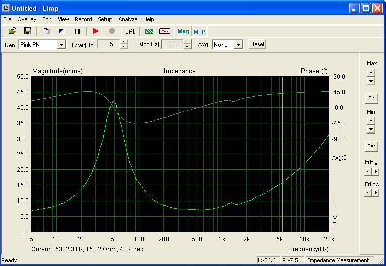
With :
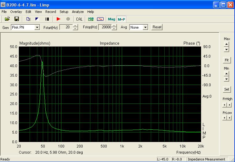
(from this site even if i don't like it too much : conception des enceintes HI-FI, Sono, Home cinéma et Car Audio, ampli filtrage actif passif haut parleur)
So, maked like it, it effect audio bandwith. As speaker inductance itself on his own when it is already high. Big subwoofer (cheap...) can start getting their inductance rising at only 150-200hz (ex : 8ohm/le=3,5mh/re=6,5).
The problem is not so much about damping, or impedance rising. But about effect on phase, and moreover when using (either active or passive) crossover to get each way more or less in phase.
Curves answer partially by themselves : it's curve of a mid-high speaker so phase faster change of phase around 50hz is not problematic...but should be for a sub/
In hornresp using filter wizard, it doesn't seems to affect anything else than flattering impedance ...but don't know if it is simulated well...?
Making this way, there is no more impedance rising. I found part of answer :
Without:
With :
(from this site even if i don't like it too much : conception des enceintes HI-FI, Sono, Home cinéma et Car Audio, ampli filtrage actif passif haut parleur)
So, maked like it, it effect audio bandwith. As speaker inductance itself on his own when it is already high. Big subwoofer (cheap...) can start getting their inductance rising at only 150-200hz (ex : 8ohm/le=3,5mh/re=6,5).
The problem is not so much about damping, or impedance rising. But about effect on phase, and moreover when using (either active or passive) crossover to get each way more or less in phase.
Curves answer partially by themselves : it's curve of a mid-high speaker so phase faster change of phase around 50hz is not problematic...but should be for a sub/
In hornresp using filter wizard, it doesn't seems to affect anything else than flattering impedance ...but don't know if it is simulated well...?
So, again reformulating, is there any problem trying to flattening impedance curve of a woofer using this kind of RC, in order to flatten phase response, in order to try to get phase alignement between two drivers easier ?
What you are describing is a Zobel network, what Andrew is describing is a Boucherot cell which is very commonly also called a Zobel network.
Thanks for clarification , i didn't know the difference. It seems i'have been lucky naming at the thread, ^^
a Zobel for loudspeaker driver impedance correction would normally be discussed as part of the loudspeaker crossover network design, should go into the loudspeaker box - not the amp
if you refer to Zobel in a amplifier design forum then you get discussion of the amplifier high frequency load network as described
if you refer to Zobel in a amplifier design forum then you get discussion of the amplifier high frequency load network as described
Your totally right. I made the mistake by starting thinking to the question from myref C discussions. Can the thread be moved to multiway speaker forum, or need i to create a new one ?
Can the thread be moved to multiway speaker forum, or need i to create a new one ?
It can and has been moved 🙂
Thanks !...
So, zobel for sub, is it good thing to optimize phase alignement even in active 2 way ?
So, zobel for sub, is it good thing to optimize phase alignement even in active 2 way ?
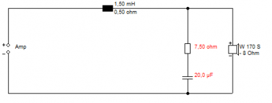
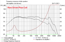
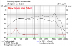
I think some pictures are worth a thousand words here. This is a Visaton W170S 170mm bass unit, 1.2mH Le voicecoil inductance and 6R DC resistance. You'd add the Conjugate circuit aka Zobel, and a bass coil as part of some modelling.
Impedance correction calculator:
Impedance Equalization (L-Pad) Circuit Designer / Calculator
Naturally, where the frequency response changes, so does phase. 😎
In practise, nobody uses Zobels in passive crossovers these days except with tweeters. They don't do much, unless you are using a SET valve amplifier which is sensitive to load. 🙂
Attachments
Last edited:
There is still not phase shown on your curves...And from what i understand, it seems that slow change of phase along frequency don't change too much response.
http://www.diyaudio.com/forums/mult...ased-method-designing-multi-way-speakers.html
So, by tweaking just a resistor, it should help phase alignement in active crossovers too.
Does this make sense ? I'm in learning process. Days after days, i'm growing slowly my knowledge a bit from nothing. So, for now, i try to make my own opinion from the little i know and read... and of course, can make stupid mistake easily.
http://www.diyaudio.com/forums/mult...ased-method-designing-multi-way-speakers.html
Active crossover don't take in account the phase response of speaker. LR 24db is theorically phase coherent. But it suppose that both speaker on each side are responding in linear phase...I know tweaking frequency of active crossover should help, but can result in adding notch too...And its not so much easy to tweak high slope crossover frequency.After reading already famous article by AllenB
INTRODUCTION: „For great sounding multi-way driver relative phase must be equal at all frequencies. Period.”
[...]
FLATTENING THE WOOFER'S IMPEDANCE: rule of thumb is to flatten with Zobel only to a some degree. Lets have it in detail. By using Zobel we get woofer impedance (and electrical phase response) ruler flat at its HF region. HF driver isn't impacted by LF driver’s Zobel so its impedance will be raising. Its phase will be shifted in the same region: Z and phase curves are following each other like twin-sisters. With flat LF impedance due Zobel at its max individual responses of both drivers in this region will be gradually getting out of phase in regards to each other ending with maximum phase difference up to 45 degrees at top end of frequency range. This will introduce unwanted additional HF cancellation and "lifelessness" in upper midrange as usually observed. That's why its usually suggested to tune R value for Zobel "by ear" by gradually increasing its value, usually without explaining the reasons why it should be done.
When we increase R value compared to „flat” version LF driver impedance curve starts to raise from being flat. With some optimal R value its phase curve will mirror that of HF driver. If phase nulls before impedance raise for both drivers luckily or deliberately are placed on the same frequency then with some particular R value of LF driver's Zobel they will get very close to being exactly in-phase at the whole top end high frequency region. Therefore individual driver responses will sum together nicely instead of response being gradually attenuated with increasing frequency as in case with totally Zobel-flattened LF impedance.
So we have are obvious gains here - electric phase gets aligned and there is less loss of HF energy for combined output (if any). Also, by increasing Zobel's R HF roll-down gets less steep for LF driver just because of less degree of shelved 1-st order filtering. It can be hard to find the best R value without seeing measured Z and phase curves, still with good ear it is possible to get pretty close. Do it by ear this time 🙂"
So, by tweaking just a resistor, it should help phase alignement in active crossovers too.
Does this make sense ? I'm in learning process. Days after days, i'm growing slowly my knowledge a bit from nothing. So, for now, i try to make my own opinion from the little i know and read... and of course, can make stupid mistake easily.
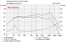
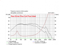
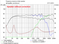
Note in the plots posted by System,
the second with single pole low pass filter, the roll-off above ~1500Hz is quite slow.
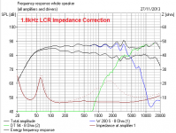
Compare the 4th plot with both the conjugate Zobel and the low pass filter, where the >1500Hz roll-off is much closer to the -6dB/octave.
Without the impedance flattening of the Zobel the filter does not work as intended.
the second with single pole low pass filter, the roll-off above ~1500Hz is quite slow.
Compare the 4th plot with both the conjugate Zobel and the low pass filter, where the >1500Hz roll-off is much closer to the -6dB/octave.
Without the impedance flattening of the Zobel the filter does not work as intended.
Last edited:
Please...since start, I have been clearly only asking for active.
I wasn't talking at all about the passively filtered curves by system7 as i already understand that it work for passive. But i should have been interested by the two other curves without passive filter if they were showing there relative phase...So zobel should help high inductance subwoofer to be in phase with mid/high, not only when using passive crossover, but with active crossover too ?
Last edited:
The Zobel doesn't affect the acoustic phase response of the driver, it's only there in passive crossovers to correct the rising impedance of the drivers so the crossover filters have a more constant load with rising frequency. Totally irrelevant for systems with active crossovers.
Mike
Mike
I totally agree with you when saying it doesn't affect phase response of the driver. It's not contradictory. Here is the point, phase response is not only the fact of a speaker...what's about amp ?
This is partially why i started this thread in amp forum, and not loudspeaker.
I've explained why i came to this question. Damping factor (so, between speaker AND amp) beeing not linear in frequency, seems to be linked with phase response of the FULL system... This is part of the specific revision C of my C ref amp (wich use great correction loop features). It is frequency compensated to get linear phase/damping... Don't understand how compensation/loop works but it's not the problem here.
Without going too much into detail, I suspect easily that this problem don't affect class d amp. As they're switching at output at regular frequency, phase should not be so much dependent of the load (but maybe output inductance filter can cause other problems). This part have already been discussed in other thread.
What i'm saying is that with high Le sub DRIVER, phase response of DRIVER isn't flat. So active crossover, even "phase coherent by itself in theory", low pass a sub DRIVER wich is non linear in crossover range, with a other way wich is phase linear in crossover range.
So the purpose i'm talking, is to make the phase of the sub-WAY(couple driver/amp) more linear before trying to low pass it actively by use of zobel.
Pretty easy to understand seeing phase response curves i shown in post #5. Same speaker/amp. With zobel added, flat phase response in mid/high range. So, in this flat phase range, it should be easier to cross with another speaker/amp flat phase response too around crossover range, either in passive or active...
Just saying "Totally irrelevant" is not enough to prove anything.
Last edited:
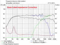
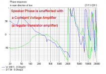
As Michael says, putting a Zobel (Here 7.5R + 40uF for 2.2mH and 6R bass) in parallel with a Woofer has no affect on phase or frequency response. A regular transistor amplifier is a "Constant Voltage Source", and the output is constant regardless of load. 😎
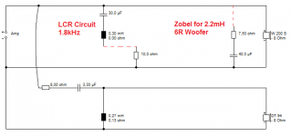
The only reason to use a Zobel is to correct impedance, which is needed with low feedback valve designs. These type of amplifiers will not produce a flat frequency response where impedance varies. With a transistor amplifier, Zobels merely waste power. There is a technique for correcting the approximate 50Hz Fs bass resonance of the system using an LCR but this is rarely seen because the component values are large. More common is correction of the midrange impedance peak, here with a 1.8kHz LCR.
These things are true with active as well as passive systems.
Attachments
I think you're confusing electrical phase shift with acoustic phase shift, they are not the same thing.
Mike
Mike
- Status
- Not open for further replies.
- Home
- Loudspeakers
- Multi-Way
- Zobel, phase & damping ... ?