Four-layer is not really too DIY, is it?
Not really 🙂, but nowadays it is not to expensive to have them made by a specialized PCB producer, and the bonus is a very high quality finish. As soon as you need some volume, having them made will(can) be cheaper then making them yourself (that is true also for 2 layer boards).
RIAA plug-board
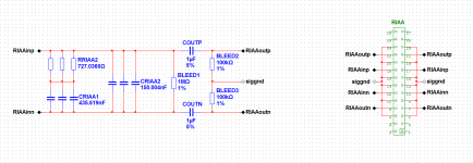
Progress report 🙂 Here is the schema and PCB for the RIAA components, please comment on those. The board size is 40x95mm (and I really would not like to change that 🙂). All capacitors have an area of 10x34mm and 2 arrays of holes, one line-array at 2.5mm intervals and one line-array of 2.54mm intervals. The line have each 2 x 6 holes (for each line-array). The capacitors and resistors can be surface mount.
Progress report 🙂 Here is the schema and PCB for the RIAA components, please comment on those. The board size is 40x95mm (and I really would not like to change that 🙂). All capacitors have an area of 10x34mm and 2 arrays of holes, one line-array at 2.5mm intervals and one line-array of 2.54mm intervals. The line have each 2 x 6 holes (for each line-array). The capacitors and resistors can be surface mount.
Attachments
Not really 🙂, but nowadays it is not to expensive to have them made by a specialized PCB producer, and the bonus is a very high quality finish. As soon as you need some volume, having them made will(can) be cheaper then making them yourself (that is true also for 2 layer boards).
Well, the good things is that it does help create group interests and group buys, which at least goes against this individualistic world we live in. 😉
Well, the good things is that it does help create group interests and group buys, which at least goes against this individualistic world we live in. 😉
Good enough for me 🙂 (which at least goes against this individualistic world we live in.)
Last edited:
Progress report (I know it is developing slow)
Sorry to be (again) a bit slow, but on one of my professional projects I have a major mile-stone coming up (could be life changing 🙂). Any way this lows everything down.
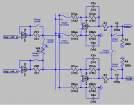
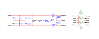
The picture attached shows the high-impedance-buffer followed by the line-driver stage. The line-driven can be configured for balanced or unbalanced signal delivery. It also supports a volume control.
Sorry to be (again) a bit slow, but on one of my professional projects I have a major mile-stone coming up (could be life changing 🙂). Any way this lows everything down.
The picture attached shows the high-impedance-buffer followed by the line-driver stage. The line-driven can be configured for balanced or unbalanced signal delivery. It also supports a volume control.
Attachments
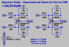
What total gain alternatives will there be with the +10 and +20dB settings? I would be fine with 55dB gain because my line-stage stage have balanced input which bypasses 2:1 input transformers for SE-BAL conversion. So there i already have enough gain 🙂
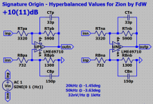
The gain in the RIAA is (about) 40dB (@ 1kHz) so these two will allow for 50 or 60dB total gain, I could do a 5 and a 15dB version also (if needed).
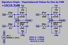
A 15db version would suite me perfect, because my linr-stage stage gives 12dB gain at balanced input - where actually 0-6dB would be enough. My pass XA30.5 does already have enough gain on the output as is 🙂
A 15db version would suite me perfect, because my linr-stage stage gives 12dB gain at balanced input - where actually 0-6dB would be enough. My pass XA30.5 does already have enough gain on the output as is 🙂
At your service 🙂 15.3dB
Attachments
Progress (again) 🙂
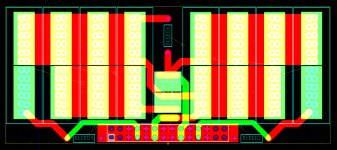
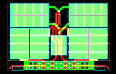
This is the RIAA-components board. It accommodates multiple capacitors and resistors. The holes for the capacitors are in rows (row distance 5mm) and the holes have a center-to-center distance of 1.25mm. Besides through-hole components the board accommodates smd parts.
The board size is 60 x 40mm, the areas for the capacitors are 22 x 13mm and 22 x 17.5mm. That should be ample space for several capacitors.
Any comments, please let me know 🙂
Attachments

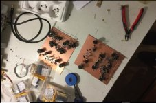
I am building a point to point version of the final schematic. Maybe it is ready at the end of this year.
I reset the engine. Star shape ger druide. everybody that sends a shorter reply gets a piece of art for free. i even set a .
Of the current Zion ? Maybe we have already posted here, at least in pieces. Will talk to Frans.
Thank you, I saw a schematic in the beginning of the thread but did not completely understand it 🙂
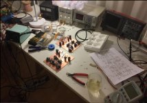
This is just a small analog lab but it is sufficient for most things. I have better and faster Scopes, FFT Analysers and other stuff.
What i really like is the DDS generator and it is fast, up to 20MHz.
I love the " Auto " knob on the scope.
What i really like is the DDS generator and it is fast, up to 20MHz.
I love the " Auto " knob on the scope.
- Home
- Vendor's Bazaar
- Zion, a ready made Phono Stage by the Paradise team