I didn't find any threads about zero grid bias when I searched, so here's one:
I like to bias the input tube with a quasi-differential circuit and not have to use a by-pass cap on the cathode resistor. But, it has always looked so tempting to zero bias the input grid and not have any cathode circuit and have better linearity. The iFi micro DSD apparently has a dc coupled output (amplifies 1 hz signals the same as 1khz) and probably won't mind sinking a milliampere or so sometimes. And it has around a 1 ohm output resistance so bias runaway should not be a problem.
Yes it does work. In a relatively quick test, playing music for 10 minutes there was no bias shift and the iFi is still working. And I got rid of the volume control circuit. I really don't like volume control circuits. Better to have them be someone else's problem.
Next simplification is replacing the cathode circuit on the output tube with a LM317L type small 3 terminal regulator and either 2 resistors for fixed bias or 1 resistor and a pot for super simple bias adjustment. And no cap needed. Need parts for that.
"....to bias the input tube with a quasi-differential circuit......"
Of course it is me that lacks understanding but can you please supply
a rough sketch what you are meaning here?
Thanks.
Of course it is me that lacks understanding but can you please supply
a rough sketch what you are meaning here?
Thanks.
My fault, was doing something else.
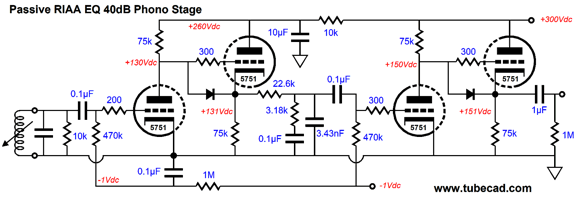
Here's what I am calling the quasi-differential input topology. The right side tube could be used as feedback if the shared cathode resistor worked better as a constant current source. It's the primitive form of a differential circuit. It's used in some of the old instruments that I support at work, albeit in transistors. I don't know the proper name for this. If anyone knows, please post.
I'm too lazy and cheap to use cathode bypass caps. And I don't worry about "capacitor" sound and I get low frequency to dc, effortlessly. It's just a hobby.
Seriously, just getting back into this hobby after a long break. Have been using the quasi-differential for about a week, and the zero-bias for 10 minutes. I had used the quasi-differential brieflly several years ago, and had noted the bass response, but was trying to use it as a fully differential stage. So, too early to tell what problems these add, if any.
Attachments

Well, that last drawn circuit diagram is simply a differential stage according to me. It is a mystery for me why you are calling it "quasi", but anyway I personally do not see any problems which have to be faced. If you choose some twin-triode (ECC81) and determine at which DC currents both triodes have to operate, everything can be calculated (or simulated).
The zener bias is the closest in simplicity and no degeneration and gets to dc. I've used it before, but I don't think I was happy with it's regulation (foggy memory) and definately the effort to get the right bias. I have not measured the quasi-differential regulation.
My understanding is that degeneration reduces excess gain (and input impedance if it were a transistor), but not distortion as there is no gain and error differencing. However, if the cathode resistor is present, it can be used for global negative feedback from a non-inverting output.
My understanding is that degeneration reduces excess gain (and input impedance if it were a transistor), but not distortion as there is no gain and error differencing. However, if the cathode resistor is present, it can be used for global negative feedback from a non-inverting output.
quasi - because
I was calling it quasi because without the constant current biasing it's not a very good differential amplifier.
I was calling it quasi because without the constant current biasing it's not a very good differential amplifier.
I was calling it quasi because without the constant current biasing it's not a very good differential amplifier.
O.K. but it still is a real differential amplifier with a perhaps poor common mode rejection ratio (CMRR).
A long long time ago, Pierre Loyez, France, published a power amp schematic with a "short tailed" pair at the input: both halves of a 12AU7 have their cathode connected to ground with 500 ohms resistors. Interestingly, he chose to return the feedback to the cathode, and connect the "other" grid to ground. I think he had a pattern on it, but don't worry, it's long ago and faraway 🙂
Regarding the no bias business, it's OK-ish as long as you know what you're doing. I have been running a selected ECC88/6DJ8 with a 10 ohms cathode resistor as a pre-preamp for my MC cartridges, and it sounds fine. But then, it only sees a mV or so at its input. Anything approaching line level may drive the tube into grid current, and that's NOT GOOD.
Regarding the no bias business, it's OK-ish as long as you know what you're doing. I have been running a selected ECC88/6DJ8 with a 10 ohms cathode resistor as a pre-preamp for my MC cartridges, and it sounds fine. But then, it only sees a mV or so at its input. Anything approaching line level may drive the tube into grid current, and that's NOT GOOD.
Attachments
Last edited:
"Zero grid bias" implies grid current. Most signal sources can't do that. There are low mu RF tubes that are designed for zero bias, but not much advantage for MC input stage. (You could use ~ 3K resistor in the cathode to ground, ground the grid, couple an MC thru a "big"capacitor to this resistor, use 100K plate load and 200V supply, on a 12AX7. Now a low impedance has to pass thru the cap, which adds a another can-o-worms, 20uF or more would be needed.)
For that differential tube amp you could add a current source in the "tail". This could be a high value resistor to a high voltage negative supply to get 1mA or so. (-100V and a 100K resistor). The higher the resistance the better the CMMR.
Alternatively an LM334, which are like $0.80 can have a specific current set with a resistor. I never tried this in a tube circuit, but it should work. (Adding a diode in series will compensate out thermal drift. See app note from Linear Technology.) Minimum 1V drop-out is required, which can work without a negative supply, if that is a problem. Otherwise adding a few volts negative supply would help. Even a battery could be used for this supply. (A single 2/3A Lithium cell has 1500mA hours, which should last a year or so if you listen 4 hours a day. A rechargeable LiFePO4 cell, or a super cap, could also be used, but more work is needed to set up a charger.)
With a current set to 1mA (add 68 Ohm to the LM334) each tube 12AX7 type will get 0.5mA, putting 1.5V on the cathode, 150V on the plate, with a 200V supply, 100K load resistors, gain will be 100, or rather half that in a differential circuit. There is not much current in the plate circuit so it needs to be buffered with cathode follower. I would not add a RIIA filter directly to this. A 100K plate resistance circuit should not be loaded with less than 1 meg. Ohm.
Tubecad's got a lot of circuit examples to look at.
How much noise? If a moving coil a transformer would be better, essentially a noise-less voltage amplifier. There is a reason why you signal transformers in old tube equipment.
C4D02120A may be a better diode. 1.2KV and 10A.
"This is a majority carrier diode, so there is no reverse recovery charge."
$2.26 each.
"This is a majority carrier diode, so there is no reverse recovery charge."
$2.26 each.
Thanks everyone,
I like the LM334, I'll have to order some with LM317s.
I'm just messing around, and actually using the input tube for near line level signals. There maybe a milliampere of grid current, but if secondary emission is the big problem (a reliablity problem, the grid typically has a coating for secondary emission, and that's just for less than microamperes), then I would, without any proof, say that the 1:1000 current ratio between 1 microampere and 1 milliampere of grid current can be mitigated by the 1 ohm to maximum grid resistance ratio of say 1:250000. Mushy numbers, but plausible.
I have tested the circuit and it works fine using a solid state preamplifier. But I can't measure the grid current or the grid's secondary emission. Maybe I'll just let one run and see how long it lasts.
"Zero grid bias" ....... MC input stage....
Actually, an MC input is one place where zero bias makes sense. The MC source impedance is just a few Ohms. The positive grid does not come down to 1K until several tenths of a Volt positive. MC signals are VERY tiny, 10mV max. It can easily wobble a zero-bias grid that much with negligible distortion.
Also zero bias gives about the maximum transconductance you can get without significant grid current, so is a good place for a low-low-level stage.
Set plate current by choice of B+ and plate resistor. Load-line is easy.
uptick,
I sometimes use solid state current sources for vacuum tube long tailed phase invertors.
Thanks for calling my attention to the LM334, I was not familiar with it.
Just for a partial set of tradeoffs, I researched the burden voltage and minimum operating currents for different solid state current 'sources' (or in the case of long tailed invertor circuits, current 'sinks').
I did not include the current source (or sink) impedance versus frequency in the list below.
I know when I used the LM317 (plain) it worked well for the phase invertors I used it for, across the audio frequencies, and more.
LM334 as a current source:
Burden voltage is 0.9V for 100uA to 1mA (the minimum input to output volts of 0.9V, no sense resistor required, just a set resistor).
Burden voltage is 1.0V for 1mA to 5mA (the minimum input to output volts of 1.0V, no sense resistor required, just a set resistor).
Those are the lowest burden voltages I know of for a current of 100uA to 5 mA.
LM317L as a current source:
Burden voltage is 3.75V minimum including the minimum input to output volts (2.5V), plus the sense resistor volts (1.25V).
Minimum current for regulation is 2.5mA, 1.5mA typical.
LM317 (plain version) as a current source:
Burden voltage is 4.25V minimum, including the minimum input to output volts (3V), plus the sense resistor volts (1.25V).
Minimum current for regulation is 10mA, 3.5mA typical.
I have used with success HV MOSFET (~800V) together with an LM431 to regulate the current, as plate loads. A 0.5 meg resistor from +B gives enough current to drive the LM431 Cathode, and that current won't be a big deal for a driver tube. A cap can store a charge for the LM431 cathode to drive it during voltage swings.
The LM431 needs min. 400uA to work. An LND150 (500V), or similar, depletion mode FET can alternatively be used to feed the LM431 cathode. The IXTP08N100D2 can handle 1KV but I do not think it alone as a current source will be that tight, but may be worth a shot. The idea is that you select a constant current where the tube is most linear.
I used it with 6SN7 types in a phase splitter, with like 10mA each, on a 600V +B. It could swing 400 V p-p with harmonics at -60dB or less, and get very close to the rails, like withing 50V, as I can recall.
Not a solution for a long tailed pair, but very effective as plate loads. I needed this to drive 211 grids. LM431 needs to see 2.5V at the current setpoint.
The gain of the LM431 is about 1,000, and it has good high frequency response, the gain/transconductance of the FET is added to this to essentially produce a zero output i.e. a constant current. I don't think I've seen this circuit anywhere else. The LM431 can take 37V, but I included a zener to protect it and the FET gate, of about 12V, for startup glitches and such. The LM431 is widely used in feedback loops is switching power supplies to drive opto-couplers. Some have even used the LM431 as a low power audio amp. I have not calculated, simulated or measured the composite gain of the FET plus the LM431. It would be cool to know.
- Status
- Not open for further replies.
- Home
- Amplifiers
- Tubes / Valves
- zero grid bias