Question
What is the purpose of the two transistors
TR 307
TR 308
Come after the mute transistor ?
As I understand they are called
zero-digital-mutting
The IC
That is their source is SN74LV157
PIN
Y1
Y2
What is the effect on the sound
By the removing of them ?
What is the purpose of the two transistors
TR 307
TR 308
Come after the mute transistor ?
As I understand they are called
zero-digital-mutting
The IC
That is their source is SN74LV157
PIN
Y1
Y2
What is the effect on the sound
By the removing of them ?
Attachments

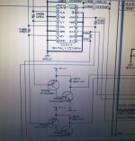
They are to mute either left or right channels and work independently of the main muting transistors.
They are to mute either left or right channels and work independently of the main muting transistors.
In my project I removed the 4 mute transistors
It had a very positive effect on sound
So no problem also remove these transistors TR307. TR308
??
You would have to try it and see. They are there for a reason and there will be some conditions or disc or user scenario that needs them.
Is it a CD player or a DVD player/recorder ?
Is it a CD player or a DVD player/recorder ?
DVD DENON 3910You would have to try it and see. They are there for a reason and there will be some conditions or disc or user scenario that needs them.
Is it a CD player or a DVD player/recorder ?
That made it comprehensive project of rebuilding for two months
Thought so. The L/R muting option is needed for certain playback conditions (which you may not need)
Thought so. The L/R muting option is needed for certain playback conditions (which you may not need)
I use the device mainly
Listen to SACD and DVD AUDIO
What situations
Can you explain please?
I think for languages where a disc might have different on each channel and you want to mute one or the other.
I think for languages where a disc might have different on each channel and you want to mute one or the other.
Thanks bro
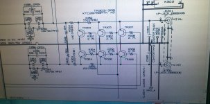
Basically I made audio circuit short route
from the OP AMP LM4562
To 10UF capacitor MKT
30 kohm resistor in parallel
150 ohm Resistor in Serial
took off two transistor mute in the route
470PF capacitors in parallel just before the RCA port
That sounds OK 🙂 although not sure about the 30k in parallel. In parallel with what ?
You want opamp output connected to 150 ohm and 10uf. That's the feed to the output sockets. 30k (its a bit low) then connects across the output to ground. The 470pf goes across the 30k.
You want opamp output connected to 150 ohm and 10uf. That's the feed to the output sockets. 30k (its a bit low) then connects across the output to ground. The 470pf goes across the 30k.
That sounds OK 🙂 although not sure about the 30k in parallel. In parallel with what ?
You want opamp output connected to 150 ohm and 10uf. That's the feed to the output sockets. 30k (its a bit low) then connects across the output to ground. The 470pf goes across the 30k.
30 KOHM Resistors -R348 R349
In parallel
There have been a circuit
After they were two resistors 150 OHM - R352. R350
I left Only one left at route and (And bridged the gap) R352
Then 470PF parallel capacitors
no oscillation
Hearing in the Danon 3910 is perfect
Attachments
Last edited:
The 150 ohm and 10 uf are in series so no real problem in the order of those two. Putting the resistor first isolates the opamp from stray and circuit capacitance that can be a cause of instability with some opamps although the 4562 should be OK.
The 30k "ground references" the output. So before or after the 150 ohm doesn't matter at all.
I said its value was a bit low because to use in combination with a 10uf cap because it forms a high pass filter of just over 0.5hz compared to the originals 0.05hz (C351 at 100uf and 30k) although when you say it out loud, -3db down at 0.5 Hz is low enough although that figure will be modified by the input impedance of whatever the player connects to. For example, working into a 10k volume control would see that frequency rise to over 2 hz (10k and 30k in parallel)
The 150 ohm and 10 uf are in series so no real problem in the order of those two. Putting the resistor first isolates the opamp from stray and circuit capacitance that can be a cause of instability with some opamps although the 4562 should be OK.
The 30k "ground references" the output. So before or after the 150 ohm doesn't matter at all.
I said its value was a bit low because to use in combination with a 10uf cap because it forms a high pass filter of just over 0.5hz compared to the originals 0.05hz (C351 at 100uf and 30k) although when you say it out loud, -3db down at 0.5 Hz is low enough although that figure will be modified by the input impedance of whatever the player connects to. For example, working into a 10k volume control would see that frequency rise to over 2 hz (10k and 30k in parallel)
Thanks bro
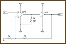
I now started a new project for 2900 DENON DVD
I already finished the restructuring of the power supply
And I am in the process of construction of the audio circuit
I did pretty much the same thing like the 3910
Only that the OP AMP OP275 (buffer op amp)
I replace the AD826
I plan to do the OP AMP AD826
bias class a
With pull down resistor
Do you have any tips
About the process of selecting the resistor value ?
🙂
Attachments
Last edited:
Keep well within the opamp current capability (remember to calculate the resistor value by taking the opamp output as Vcc, not 0v).
Keep well within the opamp current capability (remember to calculate the resistor value by taking the opamp output as Vcc, not 0v).
Thanks 😎
I have another question
My project for 2900 DENON DVD
I changed the OP AMP -IC216.IC217
OP275
To AD826
And removed the mute transistor DSP / PCM
TR 231
TR 232
My question I think to remove the resistor 47KOHM
R390
R388
Bridge
Instead the resistors
Which means that the track will resistor 1k
Capacitor 22UF
Can anyone recommend a solution ?
Attachments
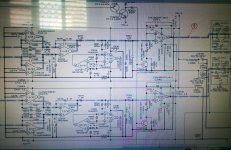
Now then 🙂 those transistors aren't for muting. They alter the voltage gain of the opamp stage from 1 to 2 when they turn on. Again, its a DVD player and there will be some scenario that calls for this function.
Now then 🙂 those transistors aren't for muting. They alter the voltage gain of the opamp stage from 1 to 2 when they turn on. Again, its a DVD player and there will be some scenario that calls for this function.
A long time ago removed these transistors
My question is about the resistors 47KOHM
I think to remove them.
That's how the track will only resistors 1KOHM and cpacitor 22uf ????
If you really want to remove the 47k then you should remove the cap and 1k as well.
Technically the AC gain of that stage is 1.02 with the transistors removed. Remove the 47k and it falls to 1.00
Its up to you 🙂 You are changing things without really understanding what they are and what the consequencies of those changes are.
Technically the AC gain of that stage is 1.02 with the transistors removed. Remove the 47k and it falls to 1.00
Its up to you 🙂 You are changing things without really understanding what they are and what the consequencies of those changes are.
I asked this because the project I did on DVD 3910If you really want to remove the 47k then you should remove the cap and 1k as well.
Technically the AC gain of that stage is 1.02 with the transistors removed. Remove the 47k and it falls to 1.00
Its up to you 🙂 You are changing things without really understanding what they are and what the consequencies of those changes are.
This location is missing transistor (open)
And resistors where the 0 ohm
Can you help me from your experience
What is most recommended
After I removed the transistors
Do not touch the 1K resistors. 47K. And capacitors 22UF
Or something else???
- Status
- Not open for further replies.
- Home
- Source & Line
- Digital Source
- zero-digital-mutting transistor