Santi,
You are welcome.
Pleased that you found the solution. 🙂
The reason of 221R (or other optional value) is mainly to limit the maximum volume level. Everywhere, we have naughty kids around. While we enjoying the music on our headphones, relaxing with absent eyes, the naughty kids sometimes sneak in and turn up the volime knob to the end, enjoying the surprise to our ear pain. We need to feel our own responsibilities for our healthy ears.
Enjoy the music! 🙂
Regards
Submitted for your approval JH...
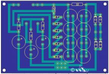
As an exercise for myself, I decided to try designing a PCB of your Zeny variation. If I can, I'd like to ask for your help reviewing the design, as well as the help of the community. I'll attach the pcb art work, schematics, and my digikey shopping list.
Oh, and for that 221ohm resistor on the output, I think I remember reading that for a head phone amp (and general impedence matching) the output impedence should be lower than the impedence of the headphones. I'll be using mine with a pair of Grado's (32 ohm), so I'll likely jumper that spot, but for the purpose of a general pcb, I left it in.
Cheers,
-Scott
Attachments
🙂
Who will stop . . . ?
This project is a returning-the-favor to diyAudio community as a result of
valuable lessons especially from the energetic Pa Pa, Nelson Pass, and also
other great contributors.
I hope that PCB experts will join you with any kind of advices.
Particularly with headphone amps, I do focus on the quietness upon no signal
so that I do my best to have a good grounding arrangement.
O, I use two thermistors (CL60 is okay I think): one at the primary
side of the transformer and another between the star ground
and the chassis. The chassis is directly connected to the
protective earth (of the wall power socket).
The ground plate in your supply PCB would work well, no doubt.
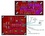
By the way, I am approching in a different way without having
the ground plate. Refer to the attached example (from another
project). You will see the star ground and branches from it.
This also works well.
side of the transformer and another between the star ground
and the chassis. The chassis is directly connected to the
protective earth (of the wall power socket).
The ground plate in your supply PCB would work well, no doubt.
By the way, I am approching in a different way without having
the ground plate. Refer to the attached example (from another
project). You will see the star ground and branches from it.
This also works well.
Attachments
Ah okay. Yeah, proper grounding methods is something that I'm still learning about, and unfortunately it's like the most important part of a circuit!
If I go with my ground plane on my pcb, should I add a pad for the chassis ground on the amplifier pcb?
-Scott
If I go with my ground plane on my pcb, should I add a pad for the chassis ground on the amplifier pcb?
-Scott
adolphe said:If I go with my ground plane on my pcb, should I add a pad for the chassis ground on the amplifier pcb?
Scott,
Indeed, I always spend more time in grounding methods than others.
I think I need time for me to understand what is "the pad for the chassis."
With your PCBs, I would try the grounding this way.
(Sure, this is not an only way . . . 🙂 )
Regards
Attachments
Those boards are great looking, adolphe. Any chance to have a PDF in B/W of those tracks when you are done, finetuning? Sure would be nice to compare the Zeny to an original downscaled Zen HP amp😉 Furthermore, I need a few projects for this winter. If the summer ever stops that is.
Steen😎
Steen😎
sorry JH, all I meant by the "the pad for the chassis" is to provide a spot to connect the chassis (through a thermistor) to the pcb.
Steenoe, I'm glad you like the layout. When I get home from work tonight, I'll try to get you a high quality B/W PDF.
Steenoe, I'm glad you like the layout. When I get home from work tonight, I'll try to get you a high quality B/W PDF.
steenoe said:Those boards are great looking, adolphe. Any chance to have a PDF in B/W of those tracks when you are done, finetuning? Sure would be nice to compare the Zeny to an original downscaled Zen HP amp😉 Furthermore, I need a few projects for this winter. If the summer ever stops that is.
Steen😎
yo,mate-you are really something!
!

?? I dont think so😉 So far (when winter comes around) I am gonna finish my A-X's and build the Babbelfish. Thats my only plans for now, so you can tell this is gonna be one boring winter😀 Ofcourse I will attempt the new preamp that NP promised us, also 😀 Thats 3 projects, so not that much🙂 A little headphoneamp would be a nice addition indeed🙂yo,mate-you are really something!
Steen🙂
Steen,
Here's the pdf's. Let me know if they're good enough quality for you. I'm new to this stuff 🙂
http://www.mcaficionado.com/diyaudio/mono.pdf
http://www.mcaficionado.com/diyaudio/psu.pdf
-Scott
Here's the pdf's. Let me know if they're good enough quality for you. I'm new to this stuff 🙂
http://www.mcaficionado.com/diyaudio/mono.pdf
http://www.mcaficionado.com/diyaudio/psu.pdf
-Scott
Oh, JH, question for you, have you tried using your zeny as a preamp? If so, how was it? Would there be any problems in using it as a preamp as well as a headamp?
adolphe said:Oh, JH, question for you, have you tried using your zeny as a preamp? If so, how was it? Would there be any problems in using it as a preamp as well as a headamp?
Hi Scott,
The concern is that Zeny has 0dB gain.
My current pre is balanced variation of Zeny with gains.
(Not released to the public as the design is still a trial version.)
BTW, please note that the concept of the grounding above is assuming
that both the amp and the supply PCBs are floating above the
chassis by the thermistor bridge between the PCBs and the chassis.
steenoe said:A little headphoneamp would be a nice addition indeed🙂
Little . . . but BIG.

- Status
- Not open for further replies.
- Home
- Amplifiers
- Pass Labs
- Zeny based on Nelson Pass cascode design