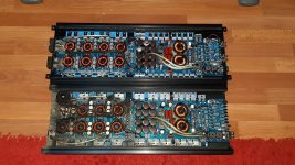
Hello everyone! Today I would like to ask a question about a defect of the zenon amplifiers (as in the photo) such as 3.5kw 5.0kw and probably also the larger models.
I'll explain in detail.
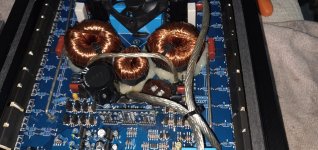
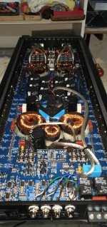
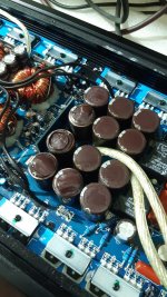
In the past few days, they have delivered 9 amps like the ones in the picture, all with the same defect, failed rail capacitors. Some turn on and continue to work, others instead remain in protection, 1 instead has the power supply completely failed (probably the rail capacitors have exploded and have also gone into short circuit, forcing the power supply to explode completely) but all, have the audio section intact.
The thing is very strange, 9 equal amps, all with the same defect.
So asking around I realized that it is a common defect of these amps, indeed, in the past I have happened to repair some amps that use the same audio driver board (ZNCM) which however had the significantly higher rail voltage and brand capacitors and higher values (FANGZE !?).
In these great amps, I solved by changing the capacitors with some of the same value, but different brand and model (nichicon) of excellent workmanship and they no longer exploded.
While these 3.5k and 5.0k ones seem to want to explode all the capacitors I replace.
Some say there is a defect in the driver board of the psu, others say there is a defect in the driver board of the audio section, others believe that it is a problem with the feedback line (R10 on the amplifier board in the immediate vicinity driver board, 220k resistor, how can a normal 220k resistor working properly cause such a big problem?) I don't know exactly what happens, but I can share my following experience, because in the past I have repaired an amplifier similar that was entrusted to me because it was completely shorted, both audio and power supply, but the capacitors were ok:
- i installed IRFP1405 + BD439 / BD449 in the power supply using 15ohm gate resistors.
- I used FDA24N40F in audio, redone the audio driver board and replaced the drivers (buffers) with BD139 + BD140 (which worked perfectly) (some might think they are slow or not very powerful, in my case they worked without problems, maybe even better than the originals).
The result is that that amplifier is still working great everyday for the past 1 year, never exploded again, never returned, never a problem again.
Could it be a driving problem on the part of the original buffer transistors? What do you think?
i've posted here some photos of the problematic amp and
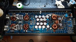
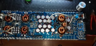
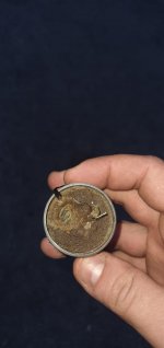
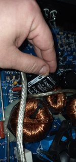
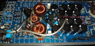
some photos of a bigger amplifier that I have repaired in the past (which used the same driver board and FANGZE rail caps) where you can see the capacitors it fitted and the ones I fitted as a replacement, never again had problems.
I'll explain in detail.
In the past few days, they have delivered 9 amps like the ones in the picture, all with the same defect, failed rail capacitors. Some turn on and continue to work, others instead remain in protection, 1 instead has the power supply completely failed (probably the rail capacitors have exploded and have also gone into short circuit, forcing the power supply to explode completely) but all, have the audio section intact.
The thing is very strange, 9 equal amps, all with the same defect.
So asking around I realized that it is a common defect of these amps, indeed, in the past I have happened to repair some amps that use the same audio driver board (ZNCM) which however had the significantly higher rail voltage and brand capacitors and higher values (FANGZE !?).
In these great amps, I solved by changing the capacitors with some of the same value, but different brand and model (nichicon) of excellent workmanship and they no longer exploded.
While these 3.5k and 5.0k ones seem to want to explode all the capacitors I replace.
Some say there is a defect in the driver board of the psu, others say there is a defect in the driver board of the audio section, others believe that it is a problem with the feedback line (R10 on the amplifier board in the immediate vicinity driver board, 220k resistor, how can a normal 220k resistor working properly cause such a big problem?) I don't know exactly what happens, but I can share my following experience, because in the past I have repaired an amplifier similar that was entrusted to me because it was completely shorted, both audio and power supply, but the capacitors were ok:
- i installed IRFP1405 + BD439 / BD449 in the power supply using 15ohm gate resistors.
- I used FDA24N40F in audio, redone the audio driver board and replaced the drivers (buffers) with BD139 + BD140 (which worked perfectly) (some might think they are slow or not very powerful, in my case they worked without problems, maybe even better than the originals).
The result is that that amplifier is still working great everyday for the past 1 year, never exploded again, never returned, never a problem again.
Could it be a driving problem on the part of the original buffer transistors? What do you think?
i've posted here some photos of the problematic amp and
some photos of a bigger amplifier that I have repaired in the past (which used the same driver board and FANGZE rail caps) where you can see the capacitors it fitted and the ones I fitted as a replacement, never again had problems.
Attachments
-
 IMG-20201018-WA0090.jpeg715.8 KB · Views: 215
 -
 IMG-20200615-WA0061.jpeg737.6 KB · Views: 123
 -
 20200615_220009.jpg549.6 KB · Views: 182
 -
 IMG-20200523-WA0110.jpg63.6 KB · Views: 115
 -
 IMG-20200523-WA0109.jpg65.5 KB · Views: 118
 -
 IMG-20200523-WA0112.jpg204.2 KB · Views: 107
 -
 IMG-20200523-WA0111.jpg196.3 KB · Views: 198
 -
 IMG-20200523-WA0108.jpg144.8 KB · Views: 216
 -
 20200530_183311.jpg829.5 KB · Views: 203
 -
 IMG-20201207-WA0004.jpg249.5 KB · Views: 216
Last edited:
For me, reading one long block of text is difficult. If that block would have been broken every time the topic changed, it would have been much easier for me to read. For others, it may be different.
Is it blowing all rail caps or only those on the positive OR negative rail?
Have you tried testing the rail caps before they fail to see how they perform at or just above the rated working voltage?
How close is the rail voltage to the rated working voltage of the caps?
Is the rail voltage regulated?
Sorry for the text all attached, I used good punctuation and good spaces, but using the translator, he formats everything his way once translated.For me, reading one long block of text is difficult. If that block would have been broken every time the topic changed, it would have been much easier for me to read. For others, it may be different.
Is it blowing all rail caps or only those on the positive OR negative rail?
Have you tried testing the rail caps before they fail to see how they perform at or just above the rated working voltage?
How close is the rail voltage to the rated working voltage of the caps?
Is the rail voltage regulated?
Regarding your question, No, the power supply is not regulated and in the case of the 3.5k and 5k, the voltage I find on the capacitors is +/- 143v (with a 14.4v battery) which is not even remotely close to the tolerance threshold of the capacitors (or at least that which is written on the body of the capacitors) that is 200volt.
I personally run a Twisted Sounds 3.5k (4500 watt) and have done extensive research and you have hit on every speculation I have come across as well. I have not had one with this issue yes as both my twisted amp and a wolfram w4500 (same amps) did not expierence this failure.
Colin the owner of Wolfram said it was something on the PSU Driver card, however unsure of what exactly. Other techs I have spoken with said they replace blown caps R10 as well as R16. These amps have 1405 and 24n40s however first I have heard about a 15ohm gate resistor, they are 22ohm from factory. Why the change to 15?
I as well always use BD139/BD140 buffers. I plan on sticking with these amps so all information I can gather is much appreciated.
Hi, I have used (and based on the excellent result, I will use in the future) BD139 & BD140 in both power and audio.
When I repaired that amp, I used 15r resistors instead of 22 for 2 reasons:
1. originally the amplifier (never repaired) used 064n with 22ohm, logically 1405 are more difficult to drive so I assumed that I need to use slightly lower gate resistors.
2. I mounted 1405 without modifying the gate resistors and noticed a suspicious shutdown, so I found it necessary to install 15r gate resistors.
2. I mounted 1405 without modifying the gate resistors and noticed a suspicious shutdown, so I found it necessary to install 15r gate resistors.
With that said I found it odd to have had 064Ns with 22Ohm Gates, So I went ahead and looked at all these style boards I currently have, Could there possibly be another underlying problem with the shut down?
Here is my tally;
Amplifiers that came with 1405 and 22ohm Gate Resistors fitted from factory: (2) 4500Watt and a 7000W
Amplifiers that came with 064N and 47ohm Gate Resistors fitted from factory: 5000W, 7500W and a 9000W
However none of these are fitted with BD139/BD140. I had a 5000W I did fit the BDs in and know a few others that use that combo as well with no known issues/Blips on shut down.
Figured it will not hurt to mention this.
Hi Perry, I now have in the laboratory 5 amplifiers identical to this one, 4 work normally if I connect them to my power supply (they only exploded 1 or at most 2 capacitors of which I do not know if they are of the negative or positive rail, because I still have to disassemble them), another instead turns on directly in protection (this I will have to check it better.Is it blowing all rail caps or only those on the positive OR negative rail?
Have you ever had an amp like this come in with the ONLY problem being failed caps and ONLY needed to replacement of the failed caps to fully repair it?
To answer your question:
yes, I happened in the past to repair other amplifiers like that to which I only changed the exploded capacitors (only the defective ones) leaving the others still inside (agree with the stingy owner).
Some have come back with the same flaw, others are still hitting hard.
What strikes me a lot is a customer in particular, who bought 5 amps similar to this one in succession, each one replacing the previous one for the same problem (exploded capacitor) and all 5 have gone to the same end.
The fifth amplifier was taken from a car in which he played for 3 consecutive years without any problems, in his car instead 15 minutes of light music were enough.

Do you have a variac or a transistor tester that can drive full voltage into the capacitors?
On an amp with just a few blown caps, have you monitored the rail voltage with a scope to see if one rail was seeing more voltage than was being produced by the transformer input to the rectifiers?
On an amp with just a few blown caps, have you monitored the rail voltage with a scope to see if one rail was seeing more voltage than was being produced by the transformer input to the rectifiers?
With that said I found it odd to have had 064Ns with 22Ohm Gates, So I went ahead and looked at all these style boards I currently have, Could there possibly be another underlying problem with the shut down?
Here is my tally;
Amplifiers that came with 1405 and 22ohm Gate Resistors fitted from factory: (2) 4500Watt and a 7000W
Amplifiers that came with 064N and 47ohm Gate Resistors fitted from factory: 5000W, 7500W and a 9000W
However none of these are fitted with BD139/BD140. I had a 5000W I did fit the BDs in and know a few others that use that combo as well with no known issues/Blips on shut down.
Figured it will not hurt to mention this.
So do you believe that factory used drivers may be causing the problem?
Honestly, I'm not sure, but surely a transistor that responds better to on / off transients would make a difference in the overall reliability of the amplifier.
Honestly I found it very strange to see 064N in these amps (ONLY 2 FOR EACH TRANSFORMER) and since they promise to make a lot of watts, it would have been better for me to have 1405, it also caused me weird to see 22ohm resistors on the 064n, maybe a factory error on an entire production batch?
or maybe they just put what they bought cheaper? lol
The fact is that when I replaced the 064n with the 1405, I noticed that the mosfets had a very non-linear behavior during shutdown (of the mosfet, not of the amplifier) so I thought of lowering the resistor to 15ohm, in fact I got a perfect behavior, as I would have expected.
Do you have a variac or a transistor tester that can drive full voltage into the capacitors?
On an amp with just a few blown caps, have you monitored the rail voltage with a scope to see if one rail was seeing more voltage than was being produced by the transformer input to the rectifiers?
No perry, i dont have a variac or similar stuff.
And, yes, i've monitored the rail voltages of one of the 5 amplifiers and during idle working, with 13,8v battery voltage, both the rails are equally to +/- 147v and there is no way to go up even when play music hard or light (to my workbench).
I have opened one of the 5 amps that I will have to repair, here it seems that there are 4 exploded capacitors, 3 in one rail and 1 in the other rail, so the problem seems not to affect only one rail compared to another and above all it seems to be a totally problem "RANDOM".
A month ago, I repaired an identical amplifier with the same problem, but in this amplifier I replaced all the capacitors with excellent "chemicon" 470uf 200v (like the originals) only that the new capacitors are slightly higher and have a slightly diameter bottom.
It wasn't a problem, the lid is far enough away and I had no impediments closing the amplifier.
After replacing all the capacitors, I tested the amplifier thoroughly on my dyno.
My test bench is made up of 10 100Ah 12v AGM batteries and a 12v 187A mains power supply (which I can adjust at will up to 15v).
I set the power supply to 14.4v and I also used all the batteries, I turned on the amplifier, all right.
Perfect amplifier and rail voltage no more than dual 155v.
I was there for over 20 minutes, no problem.
Then I injected an 80hz signal and maximized (without distortion) the amplifier with a resistive load of first 4 ohm, then 2 ohm, then 1.33ohm.
I did not notice any problems, the capacitors remained intact and there was no explosion.
For the more curious, at 1.33ohm (purely resistive load and with a voltage drop of 1.3v, therefore with battery at 13.1v) the amplifier threw out 3.02kw without any distortion.
I thought about extending the test and letting it deliver that power for an extended period, and so I did.
3kw for over 10 minutes, over time the batteries must have run down a little, so I finished the test with a drop of about 150watt.
But the amplifier performed great and nothing exploded.
I don't know what to think.
Attachments

Last edited:
So do you believe that factory used drivers may be causing the problem?
I doubt that, I just noted it as it was brought up prior. I do not have enough knowlege or expierence to input any reasons why they do this. I am still wet behind the ears.
Honestly, I'm not sure, but surely a transistor that responds better to on / off transients would make a difference in the overall reliability of the amplifier. absolutely agree
Honestly I found it very strange to see 064N in these amps (ONLY 2 FOR EACH TRANSFORMER) and since they promise to make a lot of watts, it would have been better for me to have 1405, it also caused me weird to see 22ohm resistors on the 064n, maybe a factory error on an entire product batch? I have not seen that combo. However I have noticed the output card had made a transistion from V10 to V20 on these amps, unsure of the difference as we could not find one when I spoke with another member on here.
or maybe they just put what they bought cheaper? lol
Would not doubt that one bit, extra money there and more money when they start blowing.
The fact is that when I replaced the 064n with the 1405, I noticed that the mosfets had a very non-linear behavior during shutdown (of the mosfet, not of the amplifier) so I thought of lowering the resistor to 15ohm, in fact I got a perfect behavior, as I would have expected.
Is the problem that the relays click off then the fets drop to negative rail then to ground?
Last edited:
I'm kinda in the same position here. many amps of the same models have came into the shop here.
Question, what are the capacitance tolerances of the factory capacitators when used in high frequency supplies found in amps?
The most I can find is +/- 20% @ 120hz test info. This is found on a Nichicon capacitator pdf.
Question, so if the frequency goes up as 20-30khz switching how does it affect the tolerance?
Another question. Sorry.
What is the manufacturer using for solvents to clean the boards after soldering? Most caps don't have good protection from solvents on seals with caps under 100v. Is the seals failing while cleaning and drying out in the field under use?
just a thought.
What is the manufacturer using for solvents to clean the boards after soldering? Most caps don't have good protection from solvents on seals with caps under 100v. Is the seals failing while cleaning and drying out in the field under use?
just a thought.
- Status
- This old topic is closed. If you want to reopen this topic, contact a moderator using the "Report Post" button.
- Home
- General Interest
- Car Audio
- Zenon - what are you doing wrong?