Hello all. I have a lot of zener diodes which is difficult to read their values from. From small to big metal ones. I want to build a zener tester. Would this be a good circuit ? It can test up to 50v and trigger between 5 and 15ma.
Attachments
Last edited:
It looks fine. C1 might be a little to small, even for your small currents. The LM317AHV (that's the high voltage version) has a minimum output current (in voltage mode) of around 15 ma worst case I think. I'm not sure how that relates to using it in current source mode.
There is also the TL783 High-voltage Adjustable Regulator which is functionally very similar but can withstand 125 volts differential.
There is also the TL783 High-voltage Adjustable Regulator which is functionally very similar but can withstand 125 volts differential.
I don't like the idea of relying on a 317 for current regulation: when you connect a zener, there will be a current spike, because the regulation loop is slow.
At the very least, you should include a series resistor (a few 100's ohm) to avoid frying or damaging zeners, but using just a transistor CCS looks like a much better option: you do not need a very high static accuracy for this kind of tester; a series resistor (a few 10's of ohm) would still be a good idea though.
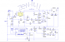
Here is a tester I made that goes to 200V, but with a fixed 1mA test current:
At the very least, you should include a series resistor (a few 100's ohm) to avoid frying or damaging zeners, but using just a transistor CCS looks like a much better option: you do not need a very high static accuracy for this kind of tester; a series resistor (a few 10's of ohm) would still be a good idea though.
Here is a tester I made that goes to 200V, but with a fixed 1mA test current:
Attachments
Thanks for the feedback guy's. Elvee you mean to put the resistor in series with the zener under test to lower the current for lower power zeners I presume. 🙂
Will a 100V Vceo NPN transistor do ? Or something like a MPSA42. I see the origional is a 400V transistor .
Will a 100V Vceo NPN transistor do ? Or something like a MPSA42. I see the origional is a 400V transistor .
Last edited:
the regulation loop is slow.
SLOW???????
Where do you see a time constant?
LM317 rules what current passes there and it's only reading voltage drop across a small value resistor.
Like any regulator, it has an internal loop compensation.
SLOW???????
Where do you see a time constant?
In the absence of a zener, it tries to force the maximum output to comply with the regulation/closed loop condition, but since it is impossible, it is saturated and when a load appears, it has to first come out of saturation and then to integrate until it actually regulates.
There is thus a short current spike at the output.
Thanks for the feedback guy's. Elvee you mean to put the resistor in series with the zener under test to lower the current for lower power zeners I presume. 🙂
Will a 100V Vceo NPN transistor do ? Or something like a MPSA42. I see the origional is a 400V transistor .
Like this, but the CCS is a better option:
Attachments


The "simple" CCS also has the advantage that you'll be able to test up to 75V zeners (avalanche in fact) with an 80V supply (and even more if your primary supply is higher)
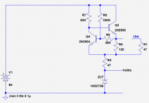
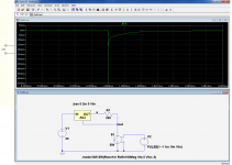
I forgot to put a limiting resistor on the transistor CCS: as soon as there is more than one transistor involved in the loop, it is a wise precaution; for a more complex (and slower) system like a complete VR, it is more than just a precaution: the sim shows the behavior of such a reg when the load is brutally switched from zero to infinity.
Don't trust the fine details, it is just a sim, and the regulator modeled is not a HV (hence the 30V supply) and is a lower current, M-version.
The reality could be better or worse, but the general outlook is correct.
Don't trust the fine details, it is just a sim, and the regulator modeled is not a HV (hence the 30V supply) and is a lower current, M-version.
The reality could be better or worse, but the general outlook is correct.
Attachments
Hallo guy's , I have a problem sourcing the lm 317 high voltage version locally.
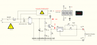
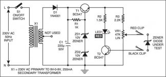
I found another circuit that looks good, but it is for a 0-18vac transformer and I want to use a 0-54Vac transformer. The output voltage is also adjustable and it has a led indicator to show the breakdown voltage of the zener under test. A lot of components will have to be changed. The transistors will be MPSA42 and the zeners Zd1/2 will be 35V zeners. I will use a 100v cap for C1. But what about the resistor values ? 🙂
Much appreciated.
Attachments
I should know the answer to this but don't, at least not without measuring some zeners... what is the leakage as the device under test approaches its marked zener value. This circuit looks way to 'fringy'. Just touching the base of the transistor will light the LED.
Values... a 54vac tranny will give around 80 volts DC when lightly loaded. 70 volt zener, lets say running at 5ma will need R1 to be around 2k2. The pot needs to be.... hold on though, here's another problem... the zener current depends on the pot setting.
Its no good as a serious piece of test gear imo. I'd test your zeners, label and bag them and forget it 🙂
Hehe Mooly, thanks a lot !😀 I have an adjustable power supply that I can use to check them. Thanks for the advise and help !🙂
- Status
- Not open for further replies.
- Home
- Design & Build
- Equipment & Tools
- Zener diode tester