The plan is to use this thread to document my integration of a Zenductor 2 stereo pair into a Modushop Galaxy 1GX388 2U chassis.
Except for removal of the tall Mosfet heatsinks, relocation of the transistors to the chassis sidewalls and reuse of the speaker posts I tried to leave the Zenductor 2s unmodified, and make the assembly as modular as possible. DC power and RCA input connections are via connectorized jumper cables. A preamp mounted to the front panel can be optionally looped into the signal path via rear panel RCA input and output connectors. I integrated two digital bias current displays and a large illuminated push button power switch into the front panel.
Heatsinks and transistors after removal:

They look a bit sad, with their legs cut off. Will they ever run again? ;-)
The amps just fit with the jumper cable connections:


Transistors mounted on sidewalls (1.4 K/W heatsinks, tested in https://www.diyaudio.com/community/...galaxy-1gx388-2u-chassis.426972/#post-7997356):

A quick test to see whether the Mosfets survived:

The 3-digit display shows the bias current. All four transistors survived, and get warm, but not hot. Definitely an improvement over the original heatsinks.
A thermal image:

Lots of filing for the bias display cutouts:

It's been a while since I had to do 'precision filing'; maybe I'll fill the gap later.
Almost finished (except for the preamp connections):


With top cover:

Rear panel, still with empty holes for preamp connections:

Except for removal of the tall Mosfet heatsinks, relocation of the transistors to the chassis sidewalls and reuse of the speaker posts I tried to leave the Zenductor 2s unmodified, and make the assembly as modular as possible. DC power and RCA input connections are via connectorized jumper cables. A preamp mounted to the front panel can be optionally looped into the signal path via rear panel RCA input and output connectors. I integrated two digital bias current displays and a large illuminated push button power switch into the front panel.
Heatsinks and transistors after removal:
They look a bit sad, with their legs cut off. Will they ever run again? ;-)
The amps just fit with the jumper cable connections:
Transistors mounted on sidewalls (1.4 K/W heatsinks, tested in https://www.diyaudio.com/community/...galaxy-1gx388-2u-chassis.426972/#post-7997356):
A quick test to see whether the Mosfets survived:
The 3-digit display shows the bias current. All four transistors survived, and get warm, but not hot. Definitely an improvement over the original heatsinks.
A thermal image:
Lots of filing for the bias display cutouts:
It's been a while since I had to do 'precision filing'; maybe I'll fill the gap later.
Almost finished (except for the preamp connections):
With top cover:
Rear panel, still with empty holes for preamp connections:
Attachments

Last edited:


The preamplifier (from ebay, using two NE5532 op-amp chips) is all wired up and works. As hoped, it puts out a little bit more than my Bluetooth receiver. For some reason the volume when streaming from a Macbook was insufficient. Must be an Apple thing?
The preamp gets looped in via two external 8 inch RCA jumper cables, which makes it easy to remove it from the signal chain.

Unfortunately one of the green 3-digit displays already fried itself and had to be replaced. At some point I'll probably switch the other display to yellow as well.

A recalibration of the voltmeters is probably in order as well.
The preamp gets looped in via two external 8 inch RCA jumper cables, which makes it easy to remove it from the signal chain.
Unfortunately one of the green 3-digit displays already fried itself and had to be replaced. At some point I'll probably switch the other display to yellow as well.
A recalibration of the voltmeters is probably in order as well.
IR images after bias adjustment to 1.13V over the inductors. The current sharing on the left side is perfect, on the right side the front transistor runs hotter.
Overview:

Left outside:

Right outside:

Right Mosfets:

Left Mosfets:

Front view, with both bias displays now in yellow:

Final wiring:

I moved the bias display ground reference to the inductor, to get rid of a 30mV offset. The cheap displays came pretty well calibrated (within 2%), contrary to what some of the reviews (on Amazon) said. Gluing the top panel nuts in place in the sidewall channels makes replacing the lid easier.
Overview:
Left outside:
Right outside:
Right Mosfets:
Left Mosfets:
Front view, with both bias displays now in yellow:
Final wiring:
I moved the bias display ground reference to the inductor, to get rid of a 30mV offset. The cheap displays came pretty well calibrated (within 2%), contrary to what some of the reviews (on Amazon) said. Gluing the top panel nuts in place in the sidewall channels makes replacing the lid easier.
Last edited:
Parts used:
To integrate the preamp:
- Burning Amp 2024 Zenductor 2 (pair), came with 16V switching power supplies (hopefully available soon in the diyaudiostore?!)
- Modushop Galaxy 1GX388 2U 330mm by 280mm by 80mm chassis https://diyaudiostore.com/products/galaxy?variant=12174834308
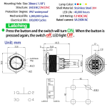
- 30mm double pole latching push button switch with ring light https://www.amazon.com/dp/B0CNYZ56ZG
- 5.5/2.5mm (NOT 2.1mm) DC power sockets & pigtail cables (2 of 3 sets used) https://www.amazon.com/dp/B0B6FFN4V5
- RCA feedthroughs (2-pack) https://www.amazon.com/dp/B004M4B7WA
- digital 3 wire 3 digit volt meters (5 pairs, 1 pair used) https://www.amazon.com/dp/B0BG31FBX5
- rubber feet (4-pack) https://www.amazon.com/dp/B08FD8TRPD
- RCA jumper cables, 6 inch, right angle to straight (pair) https://www.amazon.com/dp/B093PMLPPM
To integrate the preamp:
- NE5532 stereo preamp, single supply voltage https://www.ebay.com/itm/176909832601
- volume knob (pair, one used) https://www.amazon.com/dp/B0B375DC6Q
- insulated RCA sockets (8-pack, 4 used) https://www.amazon.com/dp/B08ZLQHGNS
- RCA jumper cables, 8 inch (pair) https://www.amazon.com/dp/B08PVSSPVM