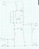
Let's start something for that purpose:
http://www.diyaudio.com/forums/pass-labs/307071-what-do-those-2sj78s.html#post5062904
http://www.diyaudio.com/forums/pass-labs/307071-what-do-those-2sj78s.html#post5062904
I may try the circuit (substituting something else for the bothersome bit on the bottom) just for the opto-mediated topside current source. The only thing that bothers me is the power dissipation in the topside current sense resistor. I will use an opto selected for controlled (relatively) CTR, commonly used in the SMPS industry.
One quibble, though - what is the value of the resistor shunted by C2? Adjust to taste?
One quibble, though - what is the value of the resistor shunted by C2? Adjust to taste?
Food for thought - I'm calling it for now the "Light Touch". Fets on the bottom are the ZVP3306A and my favorite TO-247 monster fet the IRFP260. I suppose you could use the 260 in the topside current source as well. It'll have a lower junction to case thermal resistance than the usual 240, making for cooler runnings.... The input will also be a lot easier to drive.
It'll be a while before I actually get to this design, as I want to package both my "Amp Cramp" and "Aleph McSit" projects. I'm especially interested in hearing McSit strut his stuff with a proper power supply, as he easily bottoms out my bench supply on music peaks.
I'll start a separate thread on this circuit when I actually get around to designing/building it.
Attachments
Last edited:
I suppose you're talking about the concept vs. the execution - I never won any awards for penmanship. While I have you on the line, the resistor across C2 wasn't present in the original paper at First Watt, and mysteriously sneaks in to the schematic shown earlier in this thread, with no reference designator or value - thoughts?
edit : ZM had brainfart
to try again .... I understand that as resistor altering/fine tuning Iq of (upper) mosfet , shunting opto bjt
to try again .... I understand that as resistor altering/fine tuning Iq of (upper) mosfet , shunting opto bjt
Last edited:
Wrenchone, you're talking about the resistor in the schematic in post #6 ?
If so, just disregard it. I added it myself in order to ask whether it would be smart to have it in case the opto fails in order to protect the upper mosfet
Zen Mod responded and its not needed + bothering the opto. See his reply 2 posts later
If so, just disregard it. I added it myself in order to ask whether it would be smart to have it in case the opto fails in order to protect the upper mosfet
Zen Mod responded and its not needed + bothering the opto. See his reply 2 posts later
yup
another brainfart ..... I completely forgot answering to that , and even didn't saw that I answered

another brainfart ..... I completely forgot answering to that , and even didn't saw that I answered

I might put that resistor in series with C2 instead, as sort of a protection in case the minus side of C2 really gets whacked down by a transient.
I might put that resistor in series with C2 instead, as sort of a protection in case the minus side of C2 really gets whacked down by a transient.
M2 style ?
- Status
- Not open for further replies.
- Home
- Amplifiers
- Pass Labs
- Zen with GA10JT12
