The irfp240’s all seem to be ok, checking the internal diode, d to s, g to d, g to s all tested good. The LU1014’s also seem to be good though they all test with about 3.1 M g to s and g to d. So I figure the issue must be a passive component. But what passive component could possibly cause massive current flow through R1, 2, and 3? And how does the gate of the LU1014 get any dc bias?
And thank you Kevin, the offer is greatly appreciated. Would you happen to have 8 or 10 you could sell?
Would you happen to have 8 or 10 you could sell?
It's been a long time since I've had these out. So this is what I have:

10 in a pack that hasn't been opened.
6 left in a pack that that I did mess with.
4 matched from Deep Surplus.
Please use a variac or DBT. No sense in these going up in smoke.
PM me and we'll work something out.
The irfp240’s all seem to be ok, checking the internal diode, d to s, g to d, g to s all tested good. The LU1014’s also seem to be good though they all test with about 3.1 M g to s and g to d.
If you haven't, test the mosfets with a test jig. Nelson has publish many articles. You don't have to test at operating currents, just test to make sure they operate correctly and are not broke. Read A75 article, DIY opamp article if not sure. 10 to 15 volts and drain resistor 50 to 100 ohms should be adequate. Positive voltage - resistor - to Drain. Drain tied to gate. Source to ground. Measure Gate to Source voltage.
Already tested my 1014’s and mosfets, see original post. But thanks anyway. I have 2 fixtures built, one for 1014’s and one for the mosfets.
Quick question: do the LU1014’s need to be matched in this design. I’ve never really taken time to understand the ZV9 or F3 design. What parameters are critical for this design...particularly the 1014’s.
They don’t NEED to be matched though I’m sure some builders do. But you will need to test them for determining the optimum value, minimum distortion point, for R3.
So I built a smoke stopper and it works well. Turning the amp on it immediately gets very bright then dims to nearly off. After 4-6 seconds it starts getting brighter. I turned the amp off before it reaches its initial brightness. So I figure some or all of the active devices are thermally damaged while looking just fine at low currents. Perhaps current is managing to leak from the drain or source into the gate turning it on even harder??? I’m in so far over my head it’s ridiculous but the amp sounds so good when it works that I will build a new channel point to point wired with all new parts if I must.
I would want to know two things? The voltage at the gate of Q2 and the voltage on the output, both in reference to ground.
Maybe you will have enough time to measure with the current limiter.
The initial brightness is from the power supply. The dim stage is waiting for the capacitance multiplier to turn on. The second brightness is when the circuit becomes active, then toooooooo much.
You could test the working of Q3,and Q4 by splitting the circuit in half and putting a load on it, but you would have to disable Q1 and Q2.
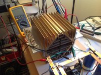
In the picture looks like R15 is discolored?
Just some ideas?
Maybe you will have enough time to measure with the current limiter.
The initial brightness is from the power supply. The dim stage is waiting for the capacitance multiplier to turn on. The second brightness is when the circuit becomes active, then toooooooo much.
You could test the working of Q3,and Q4 by splitting the circuit in half and putting a load on it, but you would have to disable Q1 and Q2.
In the picture looks like R15 is discolored?
Just some ideas?
Thanks BDP, I'm building a dedicated JFET and MOSFET up to 5 amp, 18v power supply and test station along the lines of Nelsons "Practical Mosfet Testing for audio" and "Zen Variatons #9". I should have done this years ago but I finally got tired of jumpers slipping off and test lead shorts so its time for a real hardware device. Give me a couple of days to finish the mechanicals.
I'm building a dedicated JFET and MOSFET up to 5 amp, 18v power supply and test station along the lines of Nelsons "Practical Mosfet Testing for audio" and "Zen Variatons #9"
Why build just one when I would buy a second one from you?

- Home
- Amplifiers
- Pass Labs
- Zen V9 voltage issue