Going crazy here. I have a Zen V9 I built several years ago that has worked very well until it didn't. The right channel blew Q3, lots of black stuff on the heatsink, so I replaced Q5 with a ZTX650, Q3, Q2, and Q1. I tested the LU1014D I put in with 11.3 vdc to a 20 ohm 5w resistor to drain, 1ohm source to ground, gate to ground. I get 9.65v across the 20ohm resistor and .46v across the source resistor. It all works out to .48a draw which is all my HP6215 ps can source. I also tested 4 of my 5 remaining LU1014's and the all yielded similar results.
Upon reassembling the board and applying power, (50.1VDC) no smoke, not even warm but Q2 drain runs up to 40v and the gs voltage on Q1 hits 16v before I hit the off switch. Again no smoke, P1 is a nominal 25k and adjust seemingly ok but it has no effect on Q2's drain. Ive checked R4, 5 and 6 all seem fine as are R1, 2 and 3. Caps all test good, not shorted or open at least, and all solder joints have been checked and reflowed at least.
Still on power up Q2 drain goes to 40v over 15-20 seconds and I chicken out and kill the power. I know this is a relatively ancient amp but it sounds soooo goood when it works. The left channel works as new and sounds great. Each channel has its own toroids and rectifier/filer/regulator. No voltage sag at all on power up.
I'm sure I'm just doing something stupid but after 2 days working on it I'm stumped. I can't even see how 40+ volts can get to Q2. Clearly I'm an amateur at this. Any ideas? Its the green PD DA pcb.
That Korg Nutube looks sweet!!!
Dale
WB4LIP
Whenever you mount and remount output transistors, check for shorts to the heatsink. And be careful inspecting and reusing thermal pads.
On device replacement I also replaced the littl rubber heat sink pads with new mica pads and compound. I also checked for shorting to ground because some heat sink compounds are electrically as well as thermally conductive.
https://www.passdiy.com/projects/images/content/zv9_8.png
https://www.passdiy.com/projects/images/content/zv9_8.png
Attachments
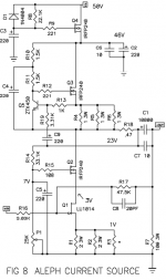
The gate of Q1 should be ground referenced through R17 and R7. The output should not be seeing DC since it is capacitively coupled by C1 and C7. With your Ohm meter measure output to ground. Check for voltage first!
Check the voltage divider R14 and P1.
This is all assuming everything is normal and there aren't more defective parts.
Get it working again. Its my favorite amp.
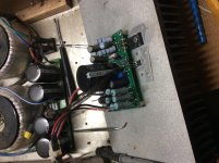
Pics of the amp could be helpful. Zen Mod, eagle eye, can spot anything.😛
Check the voltage divider R14 and P1.
This is all assuming everything is normal and there aren't more defective parts.
Get it working again. Its my favorite amp.
Pics of the amp could be helpful. Zen Mod, eagle eye, can spot anything.😛
Thanks BDP, can I take Q1 out of the circuit and power up the rest of it? I remove all active components and rechecked the passive components. R1, 2 and 3 were toast. So I put some 5w, 1ohm resistors in, 6 of them, and powered up. Immediate slight smoke and r1, 2 and 3 got untouchable hot in <3 seconds. Q1 was cool to the touch. I’m still thinking it’s a Q1 issue hence the idea to remove it and see what happens.
Not sure what pic to show, top of board, bottom of board, the whole amp??? Of course after reworking it 3 times now it’s looking pretty bad.
Not sure what pic to show, top of board, bottom of board, the whole amp??? Of course after reworking it 3 times now it’s looking pretty bad.
Check the voltage divider R14 and P1. P1 should be shorted, 0 Ohms, at turn on. If its not you could be drawing lots of current.
Did you happen to measure output to ground? Do this with the amp off.
Any pics would help.
Did you happen to measure output to ground? Do this with the amp off.
Any pics would help.
With P1 at its lowest setting the voltage to turn on Q1 an Q2 would be below the turn on threshold.
Output to ground is 100.01 ohms. P1-R14 divider will adjust between 0.1 ohms and 16.2k ohms.
Those look good
So I set P1 for its minimum resistance turned it on and measured 17v and climbing on Q1 drain and the Q1 source resistors started smoking in <3 seconds. So what does that indicate should be checked next? And thanks for helping.
Yes, Q1 is on a mica insulator and isn’t even getting warm. It’s tab shows about 0.88 ohms to ground when elevated in the air. I don’t have it clamped down in the pic but it’s stuck to the mica and heat sink, I figured good enough for a smoke test.
Last edited:
Lol, yea, probably so. I only have 1 IRFP240 left and 4 LU1014’s left, all suspect at this point.
https://www.diyaudio.com/forums/att...res-diy-pass-amplifier-amp-front-1024x765-jpg Shows the amp and inside photo I posted years ago.
Post 913 or thereabouts in the NP amp photos thread.
Post 913 or thereabouts in the NP amp photos thread.
With that voltage on Q1 you will be drawing lots of current even if Q1 is good.
The purpose of P1 is to supply about 7 volts at the gate of Q2. Q2 Vgs 4 volts, Q1 Vds 2 volts and 1 volt across source resistors.
I would remove Q2 and test.
The purpose of P1 is to supply about 7 volts at the gate of Q2. Q2 Vgs 4 volts, Q1 Vds 2 volts and 1 volt across source resistors.
I would remove Q2 and test.
I disconnected Q2 and power up with no smoke. Q3 and Q4 have 0.912 and 0.92 vds. I found R14 would vary between around 40k and 1.3M. Close visual inspection revealed nothing but upon removing it and checking under a microscope showed 2 very fine cracks on one end. So I replaced it and R18 which was discolored. I guess now I need to remove all the ‘240s and the LU1014 to verify they are all still good or not.
- Home
- Amplifiers
- Pass Labs
- Zen V9 voltage issue