Hello folks,
I got a little ZEN v4 from another fellow DIYer that said he could never make it work in an stable way, so when I got it it had all IRFP044 MOSFETs dean in one channel so I replaced them and connected it to my speakers, it sounded great but only for a couple of minutes and it died, this time the MOSFETs on the other channel died.
I installed new MOSFETs and followed the adjustment procedure and all seemed to be good, after adjustment I left both channels running for about 1 hour and it got rather hot, both heath sinks were about 63 degrees celsius and drain voltage on Q1 with reference to ground is 22V, but when I connected it to the scope I don’t like what I see, with a 1kHz sine wave and an 8 ohm load I only get about 5Vpp before it clips on the negative cycle only, there’s also a blip on the positive side, with a 100Hz wave I get a tiny bit more power and then it clips on the negative but this time the blip is not there, I also tested with 10KHz and 20KHz and those look just ugly as it does a square wave I ran for a little bit.
The power supply is shared by both channels, it has a 400VA toroidal with 94mF filtering capacitors.
What could be wrong with it?
Please see the pictures below:
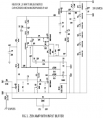
You might want to check the 4V voltage drop on the p-channel input mosfet Q4. If this voltage is around 1V (it could happen depending on specific transistor), you could come to output voltage limitation.
Thanks VladimirK,
The voltage drop on Q4 is 3.4V its a bit lower, would that be a problem?
What is the drop across Q3 (ztx450)? Is it close to the expected 0.66V? Your heatsink looks too small for the 100W dissipation this puts out and the devices are really close to the edge so the temperature is probably expected.
What is the drop across Q3 (ztx450)? Is it close to the expected 0.66V? Your heatsink looks too small for the 100W dissipation this puts out and the devices are really close to the edge so the temperature is probably expected.
Yes, voltage is spot on 0.666V and the heatsink is 280x125x60mm.

Thanks
Since you have a scope on it, maybe try adjusting R4 not for 22V but for symmetric clipping instead. I guess the other thing to consider is what are/were you driving it with. Just reading this part of the article and the odd blip in your trace has me scratching my head.
Lots of smarter people than me that can tell you what/why the square wave looks like that but not me unfortunately.
Re: the heatsink, if you are worried about the heat, try moving the devices further away from the edge of the heatsink and closer to the bottom 1/3rd rather than the top as you don't get much efficiency from the heatsink that way. Raise it slightly if it's sitting flat while you are testing so that you can get airflow below it and it will be a better representation of what it will perform like when it's built. Lastly - the fin density looks too close for best performance without a fan but in diy, the best parts are the ones you have on hand right?
Anyway, this is the section from the paper that I'm wondering if it's relevant:
In the case of Q4, the Zetex ZVP3310 performed the best among
the parts tried. The IRF9510, 9610, and similar parts worked,
but have higher capacitance, and thus higher distortion at the
top end with these input impedances. This can be improved by
lowering the values of R2 and R3. If you can accept a 10K input
impedance, you could consider using these alternate P channel
Mosfets.
While we’re talking about the input, note that the input of this
amplifier is not protected against high voltage transients. Input
voltages in excess of 20 volts will have some chance of damaging
the input Mosfet Q4.
Hope you can get this one singing loud and clear soon!
Thank You twitchie, I really appreciate you chiming in!!
So about the resistors, well that may be something since they are all the original values and not what Papa suggested on the paper.
So I want to order some ZVP3310, the ones available today are still the same right? They have the same Digi-Key part number Papa mentioned in the paper...
Thanks again!
Alex
One thing to watch out for is that the ZVP3310 has a different pin out from that
of the IRF9610. Also it seems somewhat fragile since a number of people building
the Pearl 2 (which also uses this part) has seen the part damaged. So you may
want to order extras and handle them with care.
of the IRF9610. Also it seems somewhat fragile since a number of people building
the Pearl 2 (which also uses this part) has seen the part damaged. So you may
want to order extras and handle them with care.
Oh well I don’t know why I didn’t do this before but it’s worse than I thought, output signal is lower than the input signal...
Channel 1 is directly from the signal generator and Channel 2 is the amplifier’s output, that doesn’t look right, does it??

Channel 1 is directly from the signal generator and Channel 2 is the amplifier’s output, that doesn’t look right, does it??
Any chance you have your probe multiplier switch in the wrong position?
Nope, they are both straight coaxial BNC cables and both set to 1X in the scope.
Also, the original owner used 2SC2240 instead of ZTX450 which is not exactly the same do you think that could be the issue?
I wish I had some ZTX450 handy to test...
I wish I had some ZTX450 handy to test...
It seems the 2sc2240 has a different pinout as well so not exactly a drop in replacement
for the ztx450.
Do you have any other to-92 npn transistors?
for the ztx450.
Do you have any other to-92 npn transistors?
Do you have any other to-92 npn transistors?
Yes I have a few, ZTX657, MPSA42, MPSA20, 2N5550, 2N3704, 2N5772, MPS6512, 2N3903, 2N2925.
I did more testing today and this is what I see.
1. It is actually amplifying but for some reason, most likely my ignorance, the output phase is inverted so when I connected the oscilloscope probe to the negative side of the output as per the PCB I saw the signal and yes it’s amplified almost 5 times. What could cause this phase shift?
2. I adjusted Q1 to symmetrical clipping and that’s about 40 Vpp so about 25 Watts. Sounds about right?
3. In order to get those 40 Vpp in the output I need to put about 9 Vpp in the input, isn’t that a bit too much?
Thanks,
Alex
What transistor are you using on the front end? The design is an inverting one but I'm not sure I understand if you have it connected as labelled or connected as what one would think. Output+ is actually GND in this one.
It’s using IRF9610 in Q4, 2SC2240 in Q3 and IRFP044 in Q1,2,5 all connected as per the original schematic.
Also this PCB omitted R20, there’s no connection to chassis at all.
Attached is a picture of the Oscilloscope probe connection that works, previously I was connecting the probe the other way around.

Also this PCB omitted R20, there’s no connection to chassis at all.
Attached is a picture of the Oscilloscope probe connection that works, previously I was connecting the probe the other way around.
yes it’s amplified almost 5 times. What could cause this phase shift?
Voltage amplification is approximately R3/R2, so your result is about right.
You could decrease R2 to 22kOm, in this case you will come to voltage amplification close to 10.
- Home
- Amplifiers
- Pass Labs
- ZEN v4