I have just completed my first DIY amp the Zen v4. When I borrowed a friends scope I found that a sinewave above 12kHz showed waveform distortion when compared to the input signal. The waveform showed a sharpening of the peak and and inflection point at ~1/2 V when returning back to 0V. This distortion was not affected by output levels but increased with frequency. The output of the amp was tied to a 20W 8 Ohm non-inductive resistor.
While playing with the circuit I found that by removing the 5pF bypass capacitor accros the feedback resistor improved this distortion dramatically. Whats up with this, could it be related to stray capacitance on the PCB?
Thans
Scott
P.S. Sounded much better without the cap.
While playing with the circuit I found that by removing the 5pF bypass capacitor accros the feedback resistor improved this distortion dramatically. Whats up with this, could it be related to stray capacitance on the PCB?
Thans
Scott
P.S. Sounded much better without the cap.
May be another problem
The 5 pf cap should not be that critical. As an idea try connecting with a speaker instead of the resistor and running up to see if a real world load gives the same problem.
Also are you sure those are 5 pf caps? My tester really will not work repeatabily on any values smaller than a couple of hundred pf. I have to take the bin value, the printing on the silver mica I have do not tell me what it is.
But if this is a real problem, please post your findings. I no longer have access to a signal generator and scope to check my Zen V4. If the cap is a problem sonically I will take it as a problem with the sound of the amp.
George
Do you remember what Nelson said in the Zen IV article? That cap can be made with some wire-wrap wire twisted together in a length of about an inch and a half (that would 38mm for you metric guys). He suggests then watching the response to a square wave input and trimming the length of the wires until no overshoot is seen. I think that sounds like a good practical way to trim the cap for proper response. 😎
vpharris said:Nelson suggests watching the response to a square wave input and trimming the length of the wires until no overshoot is seen. 😎
I made it for my new amp (Monolithic SuperSymmetry with Current Feedback).
It was very interesting. 😎
JH
I had also some problems with this C:
http://www.diyaudio.com/forums/showthread.php?s=&threadid=6799
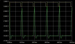
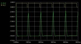
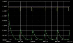
I made some simulations with 10kHz square waves and C values of 1pF 10pF and 100pF, it becoms very clear that you need this C. The right value will be somewhere between 4 and 10 pF. I think your C ist to big.
Here the waves for 1pF
Daniel
http://www.diyaudio.com/forums/showthread.php?s=&threadid=6799
I made some simulations with 10kHz square waves and C values of 1pF 10pF and 100pF, it becoms very clear that you need this C. The right value will be somewhere between 4 and 10 pF. I think your C ist to big.
Here the waves for 1pF
Daniel
Attachments
Thanks for the feedback. I have tried 2, 5, and 10pF, both silver mica and ceramic. I have not tried yet using the wire, I do have some for that very reason though. The principle reason I havn't tried it is that my signal generator produces a VERY poor square wave.
I agree that the cap should be needed for damping on high freq signals like the edge of a square wave.
Let me give you some more info. First, I made these circuit boards based on the single sided one posted on this site. I had to modify the pinout for the buffer FET since the board was designed for a different package. My concern, hindsight 20/20, is that the trace for the input signal follows along the speaker output trace for 4-5 inches or so. Is it possible that there is stray capacitance from this trace that may be providing the feedback?
The amp is very stable without the cap. Sonically, according to my wife, with the cap "the amp sounds like it is in a tunnel and without it is flowering". Description works for me if she is happy, especially when looking at the dinning room table.
Attachments
- Status
- Not open for further replies.
- Home
- Amplifiers
- Pass Labs
- Zen v4 5pF bypass cap questions.