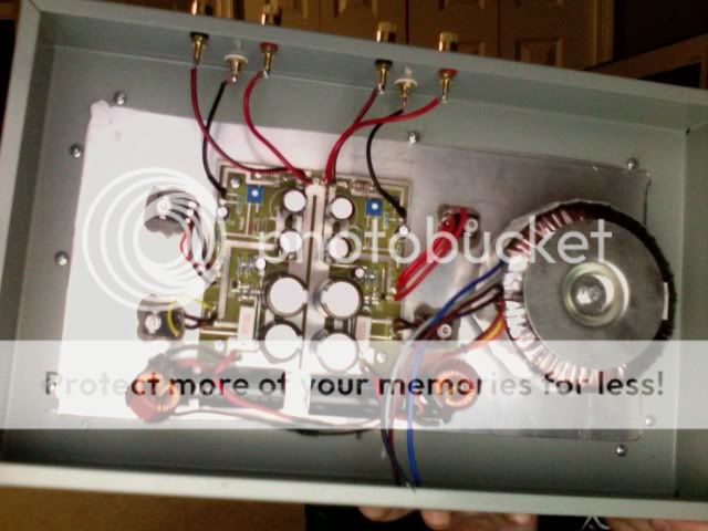
ok so i just finished my first zen amp. i biased it at 3 amps using the .22ohm resistor for r1 i also used a 30v secondary power supply with the goal of using a choke and cap. i was lead to believe after reading online that the choke would add resistance to the voltage and would reduce the input voltage back down to 34v but for some reason when i powered this puppy up i was getting 42-43v @1.4 times the rated ac secondary voltage. was there something i am missing here? so of course i assumed everything was good to go originally so i expected all to work when powered up but nothing happened. nothing got warm. nothing popped or smoked. i found power after r1 to be equal to the input power where mr. pass says i should see .66 volts. i have zero volts at the drains of the mosfets. i am so lost right now. any help would be greatly appreciated as i am tired of reading how awsome this amp will sound and want so bad to here mr. pass's creation.
note the picture is before i added the main power feed, i used a 6 amp fuse which does not blow obviously because there is no draw........?
note the picture is before i added the main power feed, i used a 6 amp fuse which does not blow obviously because there is no draw........?
Zero volts on the source resistors means no current is flowing. Zero volts on the drain means there's no power on the board.
Make sure you have all components wired correctly.
Go around with a voltmeter and make sure power is getting to the board. Do you have volts on both sides of the filter chokes?
This has got to be a very simple mistake. Just take some time and go through with a clear head - you will find your mistake.
The reason you power supply is so high is that there is no load so the caps are charging up to the peak voltage (=1.414 X rms (rated) voltage) when you start drawing your 2x3A the rail will drop.
Good luck!
Your voltage is higher than the schematic asks for, but it is not bound to be a problem.
I have played a bit around with pushing things a lot harder than the 3A 30V, and have actually found big benefits of doing so.
What I would do for a start, would be to lower the bias to 2A, to not push the envelope to hard, till you know everything is working properly. Simply replace the 0R22 with 0R33.
Once you got it running, doing as Iain says, you can see if you got enough heatsinking to push it harder. I have had a similar circuit running at above 45V at 3A bias, but the heatsinking capabilities of your chassis is crucial to success.
Magura 🙂
after checking i have found that i do have power to the board. i checked power between r1 and negative at the rectifier and it shows 42-43v.
both channels are acting exactly the same way.
i also have power at the outs of the chokes.
the mosfets are wired correctly per manufacturer's diagram which is why i had to remotely wire them to correct the piouts.
thanks guys for the help! please if you have any other ideas let me know.
both channels are acting exactly the same way.
i also have power at the outs of the chokes.
the mosfets are wired correctly per manufacturer's diagram which is why i had to remotely wire them to correct the piouts.
thanks guys for the help! please if you have any other ideas let me know.
ok i screwed up here. i do have power at the drains. the power is the same as the input power bu the amp isnt drawing any current. any new ideas?
It is apparent that this is being conducted via email to me as well, so I
officially move the discussion here.
Clearly with 40+ volts on the Drains Q1 is not conducting any current. What
is the Gate to ground DC voltage on Q1?
😎
officially move the discussion here.
Clearly with 40+ volts on the Drains Q1 is not conducting any current. What
is the Gate to ground DC voltage on Q1?
😎
can you post your schematic?
is it this one?
http://www.passdiy.com/pdf/zenamp.pdf
So the full 43V supply is appearing across the drain-source of the FET?
How many volts on the gate of the top FET Q2?
edit: you're in good hands now!
is it this one?
http://www.passdiy.com/pdf/zenamp.pdf
So the full 43V supply is appearing across the drain-source of the FET?
How many volts on the gate of the top FET Q2?
edit: you're in good hands now!
Just a thought, I have seen people turn the board upside down, and hence getting the mosfets mounted mirrored.
Make sure it's the source pin of the 9240 that is connected to the power resistor, and that the drain pins of the 9240 and 240 are connected.
Magura 🙂
Make sure it's the source pin of the 9240 that is connected to the power resistor, and that the drain pins of the 9240 and 240 are connected.
Magura 🙂
ok the gate at Q1 on both channels shows zero volts when the negative probe is on the negative out of the choke and /or the negative out of the bridge rectifier. there are 0 ohms between ground and the gates of Q1 on both channels. if i put the negative probe on the gate/s and positive probe to positive out of the choke i read @43v--- rated power in
are you saying R1 to source of Q2? because the diagram i saw on the passdiy zen amp shows gate of Q2 going to R1
both of the drains are connecting from both fets
i am using 140's not 240's juat so we are on the same page
both of the drains are connecting from both fets
i am using 140's not 240's juat so we are on the same page
0 volts on the Gate of Q1 means no bias for Q1, and explains a lot.
What's happening with the resistors from Drain to Gate and Gate to
Ground? Is the input cap in place? Is the Zener backward or shorted?
😎
What's happening with the resistors from Drain to Gate and Gate to
Ground? Is the input cap in place? Is the Zener backward or shorted?
😎
fligti91 said:are you saying R1 to source of Q2? because the diagram i saw on the passdiy zen amp shows gate of Q2 going to R1
both of the drains are connecting from both fets
i am using 140's not 240's juat so we are on the same page
Yes, that's what I'm getting at. If you look at the schematic, you'll see that it's the source of Q2 that's connected to R1.
The pinout of IRFP140 and IRFP240 are the same.
Magura 🙂
gate to ground is 0 ohms or a direct short. the zeners are pointed towards the power input side of the board. when probing between drain and gate of Q1 the resistance 20k plus and keeps climbing
holy crap i think i flipped all the fets the wrong way. mr pass if you could take a close look at the pic i posted i flipped the gates and sources of all fets. was that a mistake? i thought i would need to because of the direction i mounted the mosfets
wow thanks for the help guys. im going to flip these fets and see what happens.
what direction is the safest bet on the pots on first power up?
what direction is the safest bet on the pots on first power up?
fligti91 said:wow thanks for the help guys. im going to flip these fets and see what happens.
what direction is the safest bet on the pots on first power up?
Just set the pot in the center position, it really makes no difference.
If you have not already replaced the 0R22 with 0R33, do so before you power it up, as I suspect you're gonna run out of heatsinking pretty quick if you don't.
Magura 🙂

Now to spare yourself a few blown parts, make sure you have the source of Q2 is connected to R1.
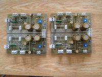
Note: The fets are not mounted the same way on both channels.
Magura 🙂
Note: The fets are not mounted the same way on both channels.
Magura 🙂
- Status
- Not open for further replies.
- Home
- Amplifiers
- Pass Labs
- zen v1 build problems????