Hi,
just try. DC shoud be the same on both sides of the speaker once powered.
Don´t know about the turn on thump though......
William
just try. DC shoud be the same on both sides of the speaker once powered.
Don´t know about the turn on thump though......
William
Hello William ,
I did try . Dc ok on both sides , no turn on thump.
Different sound , less gain , higher distorson , were the impressions ...
🙂
I did try . Dc ok on both sides , no turn on thump.
Different sound , less gain , higher distorson , were the impressions ...
🙂
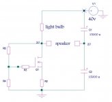
I see at least one potential problem. C1 and C2 will not divide the rail voltage evenly. Assuming that they're normal electrolytics, and rated +10-20% or some such, you should see that the voltage divides unevenly according to the ratio of their actual capacitance. The usual solution is to use a resistive divider to force equal voltage across the two capacitors. If you can manage to get the amp to set an equal DC potential--and hold it--you might have a viable circuit.
In principle you can delete the Source resistor under the MOSFET.
Grey
In principle you can delete the Source resistor under the MOSFET.
Grey
GRollins said:C1 and C2 will not divide the rail voltage evenly.The usual solution is to use a resistive divider to force equal voltage across the two capacitors.
Grey
Well they do and hold the point and dont seem to give problems . The speaker see just fiew millivolt if the DC output point is at half the rail .I was thinking of the resistive divider too and I am sure it may help in case the dc point of the amplifier isnt half the rail ( Zen V9 for example )
Regarding the possible hum , It is easy to understand that if the amp itself is well filtered ,to add two more capacitors par rail cant hurt . Infact I didnt noticed any additional hum testing that situation .
Hi,
I thought DC would be set by the left side of the amp. The speaker is just a resistor connecting the drain with the to caps on the right side. So DC will be just the same value as on the left and the offset will be zero.
William
I thought DC would be set by the left side of the amp. The speaker is just a resistor connecting the drain with the to caps on the right side. So DC will be just the same value as on the left and the offset will be zero.
William
wuffwaff said:Hi,
I thought DC would be set by the left side of the amp. The speaker is just a resistor connecting the drain with the to caps on the right side. So DC will be just the same value as on the left and the offset will be zero.
William
Indeed it is like that . But guess is not pratical to use the (sensitive ) speaker as a dc resistor ...
Good. I think wuffwaff is on the right track in that the circuit itself is able to source/sink sufficient current that it holds the node between the capacitors steady.
Don't be surprised if you get a moderate-sized pop through the speaker if you connect the speaker while the amplifier is already on. The caps will have charged to some arbitrary voltage and they'll have to equalize with the circuit through the speaker. Connecting the speaker only while the amp is off will circumvent this problem.
The resistive divider probably won't accomplish much the way things are going, so just leave it off.
Grey
stefanobilliani said:What happens connecting the Zen output this way?
You can make this work with a little modification, but realistically,
what you've accomplished is to put the capacitor on the other side
of the load.
Re: Re: Zen Output Question
Ah . . . the signal is still going through the caps . . .
Anyhow, I'm interested in.

Nelson Pass said:You can make this work with a little modification, but realistically,
what you've accomplished is to put the capacitor on the other side
of the load.
Ah . . . the signal is still going through the caps . . .
Anyhow, I'm interested in.
- Status
- Not open for further replies.
- Home
- Amplifiers
- Pass Labs
- Zen Output Question