As far as I understand it, R17;R18; R19 and C7 do not need to be removed. As Nelson said, that should work fine. So, the only components that need to be removed in order to modify ZEN V3 into a transconductance amplifier are R2 and R3 (with 1 ohm source resistor added)? R4 and R5 don't need to be altered in any way?
What about R10? Will it affect the performance in any way?
Vix
What about R10? Will it affect the performance in any way?
Vix
R10 is used to bleed DC off the output in the event that there
is no DC component to the load. You can leave it in or take it
out. As to R4 and 5, the higher their values, the higher the
input impedance and the less feedback trickles back to the input.
Practically speaking, you can leave them where they are. 😎
is no DC component to the load. You can leave it in or take it
out. As to R4 and 5, the higher their values, the higher the
input impedance and the less feedback trickles back to the input.
Practically speaking, you can leave them where they are. 😎
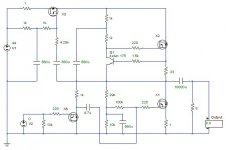
Here's a schematic. I might layout some circuit boards (using PCB123 or ExpressPCB). I already have money tied up in my Fostex attempts, why not spend some more with new circuit boards?
This acts like an upside-down source follower, whereas the source of the MOSFET creates voltage across the 1 ohm resistor. Since the resistor stays constant, output current is proportional to the resistance, this is a transconductance amplifier. A good transconductance amp will have linear amps per volt response. In this case, 1 VAC of input should cause 1 VAC across the 1 Ohm resistor, giving 1 Amp of current at the output.
It doesn't really work very linearly. The impedance of the load changes the amps per volt; it's not exactly 1:1 ratio at all load impedances.
So, it's somewhere between a voltage amp and a transconductance amp, but mostly, it's a transconductance amp.
I can't figure out how the Aleph current source doesn't act as positive feedback in this configuration. I'll think more about it ...
Attachments
I´m on the current amp/fullrange path too and I´ve decided to try tubes (direct heated pentodes) instead of mosfets.
Though, if I´d have to use mosfets I would try a choke loaded amp current feedback trough a source resistor.
Couldn´t be much more simple than that: a mosfet, a choke, a source resistor, input/output caps and a bias network.
Though, if I´d have to use mosfets I would try a choke loaded amp current feedback trough a source resistor.
Couldn´t be much more simple than that: a mosfet, a choke, a source resistor, input/output caps and a bias network.
Thanks. I'll try it during the weekend and tell you wether I like it or not. Hopefully it will sound better. Kashmire, I see that you didn't like the Fostex in the horn enclosure. Can you describe the sound? BTW, have you tried Steve Deckert's "GIZMO" (impedance/phase correction device)? I have tried to build something similar. I used 220/12V transformer. I connected Fostex in series with the secondary (12v), and 20 K ohm potentiometer accoss the primary (220v). Worth trying, sounds different...
And I assume that this works with voltage amps, not with current ones...
And I assume that this works with voltage amps, not with current ones...
Zen transformation completed🙂
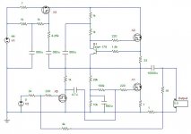
Removed Aleph current source (R17, R18, R19, C7). Removed R3, R2. Added 1 ohm 10w source resistor. Removed bleeder R10. Added relay circuit from “Zen lite” to prevent turn-on thumps. R4 and R5 stayed in place. R5 re-adjusted.
The result? Well, there’s no free lunch. With EQ network, Fostex sounds smoother. That came as a huge relief. At a cost. Gain increased substantially, and it seems to me that it clips earlier, so I assume that it has about 10 w now. Distortion has increased, but it sounds benign (tube-like), so doesn’t hurt much, just reminds me to lower the volume. I assume that it is 2nd harmonic.
But the most important thing is that I like it…(not the distortion-the amp😀)
I’d like to hear opinions of others who experimented with transconductance amps…
Best regards
Vix
Good to hear someone do some real experiments.. The 1 Ohm source transistor determines the gain. Maybe 2 Ohm would be more practical, this wou;d also drcrease distortion. Then again, you lose 2x the voltage drop across this resistor.. say 2Amps / 2Ohm = 4Volt, 4amps peak = 8Volt that you lose as maximum ouput voltage... so you might well loss some power output..
Since there is certainly a loss of power, how about trying a "balanced-transconductance-Zen", i.e. balancing two modified Zens to increase the power. BTW , it turns out that this, if possible, will become very similar to SOZ....(or something else??🙂
Nelson?
Nelson?
Vix said:Since there is certainly a loss of power, how about trying a "balanced-transconductance-Zen", i.e. balancing two modified Zens to increase the power. BTW , it turns out that this, if possible, will become very similar to SOZ....(or something else??🙂
Nelson?
YES!
🙂
I am glad that you like your Fostex NOW...
I experimented the balanced version ... mmmh I like it a lot . Waiting for the Fosatex FE206E , the Jordans plays every day in theyr GM MLTL enclosure.
At 5 amps of bias/channel the amp draws more than 300w of total power (24 volt), but it is worth it .
Comparing to a zen V4 balanced there is a lot less power avaiable , but would the JX92s take more? Anyway they can play loud enough and they play beautifully . No second armonic distorsion in balanced mode , and being no feedback amp, it turns out to be a fantastic set-up with almost every kind of music .
Even some rock material such -one of my favourites- Joe Jackson Band Vol 4 cd ,can reveal all its beauty with so small drivers .
Can wait to ear the Fostex , the MJ King MLTL enclosure go low to a 35 Hz !!!!!
Ahh ! What beautiful bass can play the current source amp :
extended.. what sens of rithm ... speed ...dynamics .
And the thing I like the most is the monotonic carachter of the class A one stage amps: magic when - at night - the volume goes down ... mmmmh !!!
🙂
Of course it reminds the SOZ if you made it a differential pair .
If there are say ,2 original Zen(mdified with a source resistor) and no connections (except the speaker)between the amps it will recall a Zenlite balanced.
😎
If there are say ,2 original Zen(mdified with a source resistor) and no connections (except the speaker)between the amps it will recall a Zenlite balanced.
😎
Hi Stefanobilliani
I haven't tried to build a balanced version yet, but I can smell that's gonna be tasty🙂 I think I won't be able to refuse😀
Although I already imagined it, it would be rather nice if you could post the schematics...
And..yes, Fe206 E plays good now, even though I think it will sound even better when I build horn enclosure....Strange speaker it is... apparently needs a lot of tweaking, but when done, you realize what was it all about

Regards
Vix
I haven't tried to build a balanced version yet, but I can smell that's gonna be tasty🙂 I think I won't be able to refuse😀
Although I already imagined it, it would be rather nice if you could post the schematics...
And..yes, Fe206 E plays good now, even though I think it will sound even better when I build horn enclosure....Strange speaker it is...
apparently needs a lot of tweaking, but when done, you realize what was it all about Regards
Vix
Horn enclosure...
Just read the NPs article ... fantastic...
... but I wouldn't spoil your fun with a schematic.
billiani / knows there's a God and a Devil

Just read the NPs article
... fantastic...... but I wouldn't spoil your fun with a schematic.
billiani / knows there's a God and a Devil
Hmm….while contemplating about horn enclosures…
At first I thought that they are going to be too big, but then, Nelson reveals “The Klein Horns”. Now I can freely say that my horns are going to be “smallish” 🙂
As for the Transconductance-Zen, I am sure that the design can evolve even further. One thing I didn’t like is the wasted energy in the Source (1-2ohm) resistor. I am wondering if it is possible to include an active current source instead of a resistor. (maybe a lightbulb will be more appropriate, at least it will glow) Hope that’s not silly. Probably someone could help me on this.
Before I went to bed last night I re-read the article on ZEN V7. Zen V7-T seems very attractive. I‘d like to find out how to modify this into a transconductance amp. But I am not sure which components should be added/removed. Any help will be highly appreciated.
Best regards
Vix
Back from my trip. Did some Zen thinking on the airplane when I wasn't asleep...
The source resistor is local feedback - it produces voltage feedback proportional to the output current. As the output current modulates, it changes Vgs by the voltage drop across the resistor (i.e. it raises the source voltage in respect to ground when current causes a voltage drop across the resistor). Since it has a steady DC current (bias current), usually around 2 Amps for the Zen circuits, it biases the source up by the steady-state voltage drop.
A 0.33 Ohm source resistor will lift the source up by 0.66 Volts when running 2A bias current. Therefore, the Vgs bias point must increase by a proportional amount. This stabilizes the bias a lot! The bias adjustment potentiometer will be much less touchy (the source resistor is local negative feedback, which stabilizes the gain, making bias adjustments much easier).
This is very similar to cathode feedback for tubes. See http://www.lundahl.se/claus_b_se.html for a great discussion on cathode feedback. Click on the building instruction link for the article. VanDerVeen from Plitron also has some info on cathode feedback. http://www.plitron.com/PDF/PB/Article/Atcl_4.pdf
Even if you don’t like tubes, these articles contain a great deal of information about cathode feedback, which functions similar to a source resistor for MOSFETs. There is much to learn about MOSFETs, even from tubes.
I wouldn’t worry about the power dissipation. A current source will probably cause a voltage drop more than 1 or 2 volts. My simulation studies show that increasing the source resistor more than 1 Ohm will increase distortion, anyway. 2 Amps at 1 Ohm is only 2 Watts dissipation. I’ve chosen to test two 0.75 or 0.82 resistors in parallel, which would result in less than 1 Watt dissipation per resistor. If you wanted to get crazy, use two 2 Ohm resistors in parallel, so each resistor would dissipate 1 Watt.
My Fostex FE207E speakers are still stacked in the garage. I’m intending to rebuild them into the recommended double-bass-reflex design. I even have the wood sitting on the table saw, whenever I get out there to cut it! I still haven’t figured out why I bought them, because all they do is sound lousy. This has given me some hope.
Hi Kashmire
Thank you for the links. Btw, after some days of listening to a modified Zen, I am no longer so enthusiatic about it. It sounds different-but now the question is if it really sounds better.
At first, I was impressed by a better bass and a midrange which did not sound as harsh as before. However, after more careful listening, i noticed that there is something strange with tonal balance. Namely, piano notes do not sound as they should. Some are much louder than others-the result is that the sound gets annoying and I simply wish to turn it off
(This is the result with Fostex working in a selad enclosure, with the Eq network as suggested by Nelson in his article. R0 =47 ohm, R1 =4,7 ohm C= 15 uF. )
Even though I was planning to build a horn enclosure, I gave up, because of building difficulties (I am not that experienced). Instead, I decided to build MJ King's ML TL (project 5). A friend of mine will help me on that. Hopefully we will do it during the weekend, and then I will try to evaluate the sound again.
regards,
Vix
Vix said:Thank you for the links. Btw, after some days of listening to a modified Zen, I am no longer so enthusiatic about it. It sounds different-but now the question is if it really sounds better.
At first, I was impressed by a better bass and a midrange which did not sound as harsh as before. However, after more careful listening, i noticed that there is something strange with tonal balance. Namely, piano notes do not sound as they should. Some are much louder than others-the result is that the sound gets annoying and I simply wish to turn it off
(This is the result with Fostex working in a selad enclosure, with the Eq network as suggested by Nelson in his article. R0 =47 ohm, R1 =4,7 ohm C= 15 uF. )
I would suggest that you scale the values of R4 and R5 upwards
so that the preamp (or whatever) isn't seeing as much of the
output signal. If you simply adjust R4, then you're still running
some voltage feedback. Also, play with the value of R0 and R1
and see if you can improve the damping and tonal balance.
Thanks Nelson🙂
Your suggestions are always welcome! I will replace R5 with...say 100 K ? And R4 with...hmmm...47 K? (or even more?)
Thanks for advice, I will try it during the weekend and let you know...
Regards
Vix
Your suggestions are always welcome! I will replace R5 with...say 100 K ? And R4 with...hmmm...47 K? (or even more?)
Thanks for advice, I will try it during the weekend and let you know...
Regards
Vix
As long as your input cap doesn't leak, you can go higher,
and the proportion of R4 and 5 are simply to set the DC
value of the output. This ratio will alter if you use a Source
resistor on the Mosfet.
and the proportion of R4 and 5 are simply to set the DC
value of the output. This ratio will alter if you use a Source
resistor on the Mosfet.
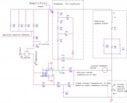
One night thougt abt current compensation
Current compensation may bee the right thing to do.
Here is one sim eksperimental pice of low pass current gain highpass current feedback, bandpass voltage feedback.
Worst of all it goes into the voltage amplifiers feedback loop.
The idea came out of looking into linkwitz greiner, and i thougt how abt using it as current feedback. At first current feedback, but then i thought how abt splitting it in a negative high sektion and a slight positive lowpass sektion. I soon realised i needed a "Q rejektion or Q low stimuli part" as a big outside series filter became a "big thing" to avoid.
som coments please !
regards
Attachments
- Status
- Not open for further replies.
- Home
- Amplifiers
- Pass Labs
- Zen current amplifier