I'm halfway through building the version with the servo. If it turns out to be noisy I'll cut it out and try again.
I can connect the servo to the SEN output rather than the DAC output - both work in spice. I now see that with the servo connected to the DAC output it only gets the bias current right; with it connected to the SEN output as you suggest I think it should adjust the bias current to compensate for drift in the matching of the quads of jfets.
Thanks for your help.
As explained in the article, the floating supply is in a separate current loop as the signal path, and then the two can be considered so.
The output impedance as well as the IV conversion gain is purely determined by the R_iv.
You can easily set up a Spice model and check this for yourself to help you to understand.
Patrick
I still don't get it, since the power source with less than 1 Ohm Ri is in parallel with the output. Whatever the current loops are, there is less than 1 Ohm in parallel with the output.
What has the power source impedance to do with the output level if the signal current does not (cannot) go through it at all ?
If the signal does not go through the PSU, and it does not, then it is equivalent to infinite impedance.
Patrick
If the signal does not go through the PSU, and it does not, then it is equivalent to infinite impedance.
Patrick
Last edited:
What has the power source impedance to do with the output level if the signal current does not (cannot) go through it at all ?
If the signal does not go through the PSU, and it does not, then it is equivalent to infinite impedance.
Patrick
Okay, thank you.
I have a piece of good news for those who have a real interest in the functioning of the XEN IV circuit.
I have come to an agreement with Jan Didden, that once the Linear Audio Volume 3 is published, Jan will make my XEN IV article in Vol. 2 available for download as PDF at the Linear Audio website.
Jan still owns the copyright of the article. So I ask you to respect that.
Patrick
I have come to an agreement with Jan Didden, that once the Linear Audio Volume 3 is published, Jan will make my XEN IV article in Vol. 2 available for download as PDF at the Linear Audio website.
Jan still owns the copyright of the article. So I ask you to respect that.
Patrick
Zen > Cen > Sen - Evolution of a Minimalistic IV Conversion Circuit
As noted by Patrick above, this article is now available for download in the Online Resources area of the Linear Audio website.
Enjoy!
jan
As noted by Patrick above, this article is now available for download in the Online Resources area of the Linear Audio website.
Enjoy!
jan
Thank you for publishing the article.
Is a battery mandatory? A power supply with transformer, rectifier and filter can be also floating to the ground.
Is a battery mandatory? A power supply with transformer, rectifier and filter can be also floating to the ground.
Thank you for publishing the article.
Is a battery mandatory? A power supply with transformer, rectifier and filter can be also floating to the ground.
I don't know whether it is significant, but the floating mains supply will have capacitance to the mains, and one end of that capacitance will be connected to the output signal I believe (don't have the circuit in front of me).
At the very least, stay away from toroids and use a small, separate-bobbin transformer.
Edit: Patrick, we x-posted.
jan
Not mandatory, but simplest to implement.
Patrick
To my view, a floating PSU isn't too complex to implement.
I don't know whether it is significant, but the floating mains supply will have capacitance to the mains, and one end of that capacitance will be connected to the output signal I believe (don't have the circuit in front of me).
At the very least, stay away from toroids and use a small, separate-bobbin transformer.
Edit: Patrick, we x-posted.
jan
The transformer's back-capacitance to the mains is mainly in high frequencies, well above the audio band. Two R-Core transformers in tandem should be more than enough. Even one R-Core transformer may well be good enough. However a grounded shield between the primary and secondary would better be eliminated.
To my view, a floating PSU isn't too complex to implement.
A suggested one was posted way back in this thread. It included a good common-mode choke, which might be augmented for really nasty HF line noise with a lower-inductance higher SRF one.
And although JFETs are usually much less susceptible to rectification of high frequency line noise than are bipolars, given enough of the crud out there these days you can still get problems.
Another item to realize: even batteries, through their ponderable size and capacitance, "see" the surrounding world, despite being galvanically isolated.
Brad
There are viable solutions to all potential problems.
An R-Core transformer with a grounded shield between the primary and secondary can eliminate a big portion of the RFI on the mains supply.
A second, tandem R-Core transformer without a grounded shield cam minimize the back capacitance to both the mains and the ground.
An hefty common-mode choke after the rectifier can eliminate most of the residual RFI.
A common-mode capacitance multiplier can serve as both filtering any residual RFI, including the rectifier's diodes switching noise, and as further isolating the supply from both the mains and the ground.
A following shunt regulator may provide as quiet supply voltage as it can get, with a very low Zout.
A good shielding of the entire PSU may be beneficial in isolating it from the surrounding environment.
Actually I'm perplexed as why the above measures aren't common practice in high quality audio gear.
SEN PCM1794 working
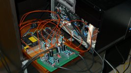
I got my SEN working.
I first tried with the servo connected to the output but the filter I put on the input of the op-amp made the servo unstable due to the current from the op-amp input developing voltage across the resistors of the filter. It would swing around a bit then lock up at one extreme.
Instead I put the servo back onto the input to manage just the 6.2 mA bias hoping that I had matched the jfets well enough for it to work. I had hacked the servo up a bit by this time trying to make it work on the output so I never actually tried the circuit I previously posted - I had already removed the filter which had caused problems with the servo on the output.
I'm pretty sure the diagram below shows the circuit I ended up with.
The new servo holds the input voltage at around -1mV on both balanced halves of each channel.
There is a little bit of high frequency noise which I guess is hardly surprising given the 5 SMPSs and computer. It does sound like switching noise.
Brief listening test did not disappoint. Now I just need to eliminate the noise from the power supplies - maybe switch to batteries and a charger circuit as described in earlier posts.
Photo shows one half each of L+R channel. Other halves are underneath.
Attachments
Firstly congratulations, if only for the courage to experiment.
Secondly in our own example, there is no noise at all.
We connect the output to a headphone amp on maximum volume, and can still hear nothing.
Try batteries first. Then you know for sure.
Thirdly I would still try to do away with the servo and just use a degenerated 2SK170 as current drain.
But well done indeed. 😉
Patrick
To my view, a floating PSU isn't too complex to implement.
That's not what he said. He said a battery was simplest. Hard to argue with that, what with all the extra issues with a floating mains supply.
But why not, it can be done, it's a matter of engineering compromises just like about ANY design decision.
jan
...and then Joachim Gerhard has o a very nice one for TINA... but still try batteries first, no doubt there!
As Patrick says.😎
As Patrick says.😎
Attachments
Last edited:
Batteries and series regulator is going to be my solution - best of both worlds!
The transformer solutions I have tried (toroids only) with SEN V18 are audibly noisy - even with two layers of regulation.
Cheers,
Nic
The transformer solutions I have tried (toroids only) with SEN V18 are audibly noisy - even with two layers of regulation.
Cheers,
Nic
R-core will improve things, but still batteries are much better.
If you do not want to use a reg after nbatteries, use a simple L-C (what I use).
Patrick
If you do not want to use a reg after nbatteries, use a simple L-C (what I use).
Patrick
- Home
- Source & Line
- Digital Line Level
- Zen -> Cen -> Sen, evolution of a minimalistic IV Converter