Tell me 😀 Floating power supplies are a nuisance and best not used in any design where DIYers are around.
Last edited:
To be clear, I did not intend laughter at darr, just at our rather nerdy puns. I'm pretty sure any DIYer worth their salt has let the magic smoke out at some stage or another. It is, as you say, best avoided.
Last edited:
Same here, I think no one laughed at darr so it seems there is misunderstanding at more than 1 side. As I wrote, the frustration of the designer as someone did not understand a pretty uncommon creation (nor the explanations) could be felt.
Last edited:
The discussion has moved far from my question:
I received an answer that I think I misunderstood:At the beginning I have to say that I am a noob. My English is also poor, but google translate helps me🙂
I read the thread but for the above reasons I have no knowledge and skills to do what I planned.
I need help to adapt the CEN to the DAC TDA1541A.
I saw several solutions (e.g. D1) and now I use an analog stage on opamps.
I know that I need to compensate offset on I-out in the TDA with potentiometers.
The DAC I have has the option of mounting pull-up(bias) resistors (R25, R33 in the picture) 2k5 which "inject" 2mA to these outputs. After using them I had a 30mV offset. It's not good as far as I understand. Could someone show me a solution that will work and adjust the CEN to the TDA1541 DAC?
Thanks a lot🙂
as I understand now: CEN IV is not suitable for TDA1541Ahttps://www.diyaudio.com/archive/bl...-out-production-pedja-rogic-ddnf-iv-stage.pdf
Right hand side of Fig. 1.
Patrick
Same here, I think no one laughed at darr. As I wrote, the frustration of the designer as someone did not understand a pretty uncommon creation could be felt.
Yes, this long-standing thread has clearly taken its toll.
darrr, it can be adapted to TDA1541. Patrick is simply pointing you to a circuit more suitable to someone who does not understand how.
My mind is confused.
There are many different circuits for the tda 1541. I wanted to try CEN IV no another one. Because it can be easily built on a prototype board, because I can test it from a battery supply , because I have a spare Jfet quad, because I wanted to compare it with the IV on the opamp and with the D1 IV.
So my question "Can this circuit be used as IV to tda 1541?" I understood Patrick's answer: "use the right side of the diagram". Well, I used it as much as I can. Now I do not know if someone used CEN to tda1541? Is it possible theoretically but nobody did it?
Following Patryk's advice, I give it up as it exceeds my level 🙂
Thanks for all for help🙂
Darek
> I give it up as it exceeds my level.
Wise decision.
If you want something discrete to compare to the D1, consider Pedja's.
https://www.diyaudio.com/archive/bl...-out-production-pedja-rogic-ddnf-iv-stage.pdf
Fixed rails, easily obtained parts, simple circuit, can be built P2P, full schematics for TDA1541, designed by a reputable audio engineer.
What more do you want ?
Patrick
... avoiding sorting out hassle with the parts 🙂. This same engineer made a circuitry that works fine in all his tda1541 converters with the opa861... though a quiet ground by a clean layout is needed. With triming to avoid dc blocking cap as well... can be seen at Audial web site. Or here if you dig...ad1862 thread.
Last edited:
OPA861 is discrete ?
Quote :
"There are many different circuits for the tda 1541......
I wanted to compare it with the IV on the opamp and with the D1 IV."
Cheers,
Patrick
Quote :
"There are many different circuits for the tda 1541......
I wanted to compare it with the IV on the opamp and with the D1 IV."
Cheers,
Patrick
No but as he said it exceeds his level I was thinking it is a good information for him ...as it is as well related to Pedja that mentionned the discrete would hardly beat the 861 aop... I have fex doubt it can beat the D1 in the tda1541 purpose.
Last edited:
Aren't we in the twilight zone of discrete/IC (when compared to an opamp) in the case of OPA861?
Last edited:
Granted I've not read the entire thread, but has anyone built the SEN I/V using BF862's?
I did a quick sim(not very good at LTSpice) adding 100R to the gates of the two fets going to GND.
Simulation looks promising, but then I'm not very good at simulation software.
I did a quick sim(not very good at LTSpice) adding 100R to the gates of the two fets going to GND.
Simulation looks promising, but then I'm not very good at simulation software.
Attachments

Hi Patrick,
Yes the dissipation is a "bit" high. I have both 2SK170 and BF862, but more of the BF862's.
I'll have to tinker some more in LTSpice when I get home again.
See how it looks with lower supply voltages etc.
Yes the dissipation is a "bit" high. I have both 2SK170 and BF862, but more of the BF862's.
I'll have to tinker some more in LTSpice when I get home again.
See how it looks with lower supply voltages etc.
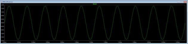
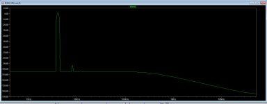
Just for fun, I did try the sim with BF862 and and a +/-12V supply.
Dissipation dropped to under 80mW and the sine and fft still looked good.
I did a quick layout with Cu zones for each pin of each jfet.
Dissipation dropped to under 80mW and the sine and fft still looked good.
I did a quick layout with Cu zones for each pin of each jfet.
I never use any transistor to more than 1/3 of max rated power.
Max rated power means 125°C above ambient at junction.
Patrick
Max rated power means 125°C above ambient at junction.
Patrick
I never use any transistor to more than 1/3 of max rated power.
Max rated power means 125°C above ambient at junction.
Patrick
I take your word for it as you are well above my skill level.
It was more a experiment, many do sudoku or crossword puzzles....me, I relax doing simulations and PCB layouts.
Jonas
As on the front cover of Linear Audio Vol. 2.
Patrick
Hi,
Where does one find that kind of heatsink?
One that thermally connects the TO-92's?
- Home
- Source & Line
- Digital Line Level
- Zen -> Cen -> Sen, evolution of a minimalistic IV Converter