Hi,
I plan to build the ZD5 project also. However, wattage ratings for the resistors and voltage ratings for the capicators, all of which form the crossover circuitry, are not specified. What ratings are required?
Many thanks.
I plan to build the ZD5 project also. However, wattage ratings for the resistors and voltage ratings for the capicators, all of which form the crossover circuitry, are not specified. What ratings are required?
Many thanks.
Zaph might be about to post a new high end design: http://zaphaudio.com/temp/ZRT-system-dramatic.jpg
This is from his blog...
This is from his blog...
Looks interesting! However, I've ordered all components from Madisound for the ZD5. Built as a sealed design, they should be ideal for a small room. I should have the components in two weeks or so. Resistors are all 10W and capacitors range up to 400V.
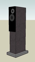
I'm planning on concrete boxes to house the drives.
Building the project as accurately as I can should lead to an interesting comparison with my MA RS6's and RS1's.
Just one question: given that inductance is a function of frequency, what frequency is normally used to measure the the inductance of crossover coils? I've searched the web for answers without success.
Ok, Most parts are here. Can finally get started.
I have decided to build the floor standers.
I'm thinking of making the front baffles 7" x 15" (maybe 20"). This will attach to the "as shown" front baffle, making the baffle 1.5". The drivers will mount to the 7x15 and it will bolt to the front panel.
Do you guys think this will cause any problems?
I have decided to build the floor standers.
I'm thinking of making the front baffles 7" x 15" (maybe 20"). This will attach to the "as shown" front baffle, making the baffle 1.5". The drivers will mount to the 7x15 and it will bolt to the front panel.
Do you guys think this will cause any problems?
Attachments
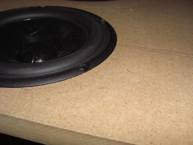
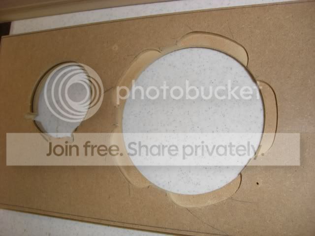
Could someone take a look at the attached pic and let me know if the change to the front baffle will be a problem?
The reason I ask is because the will be the 3/4 inch step back to the front panel. It will be at least 5" below the woofer.
Thanks!
 [/IMG]
The reason I ask is because the will be the 3/4 inch step back to the front panel. It will be at least 5" below the woofer.
Thanks!
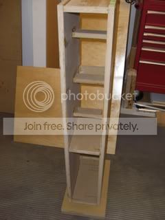
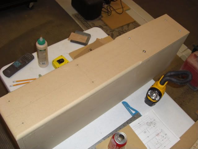
Most of the mdf is cut.
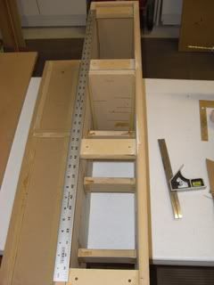
Sides, braces, top and bottom are glued together. I'm working on the removable back panel.
If I get no comment on the proposed baffle change, then it will be as Zaph designed....almost. Don't think I can do a 3/4" roundover with the router I have.
Sides, braces, top and bottom are glued together. I'm working on the removable back panel.
If I get no comment on the proposed baffle change, then it will be as Zaph designed....almost. Don't think I can do a 3/4" roundover with the router I have.
cj.9 said:Most of the mdf is cut.
Sides, braces, top and bottom are glued together. I'm working on the removable back panel.
If I get no comment on the proposed baffle change, then it will be as Zaph designed....almost. Don't think I can do a 3/4" roundover with the router I have.
I also am unable to do 3/4 roudover with my router - 1/4 drive Craftsman. While you can find 1/2 roundover bits everywhere, I was able to find a 5/8 roundover on 1/4 drive at Sears. It also takes up the full face plate clearance of the router so there was no way a 3/4 would fit if I found it. That is as close as you will get to 3/4, and if venerring should put less stress the bend than the 1/2 would. Good luck.
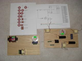
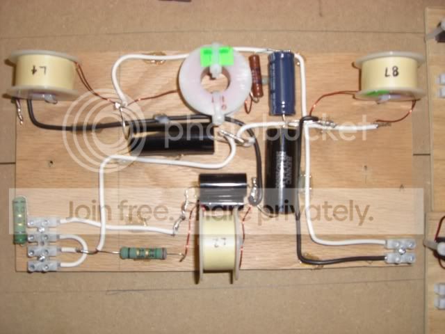
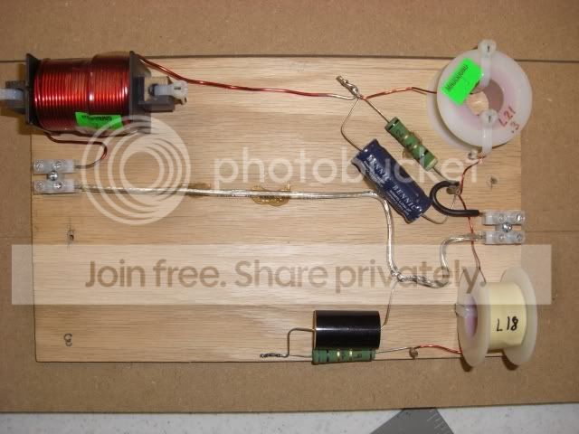
Hate to hijack (sort of) but the other thread on the SR71 build is so long with 99 posts and I see Zaph is participating in this thread. I am resisting the premade SR71 crossovers preferring to do it myself but one thing has me confused. The schematic shows 2 resistors no part of the inductor, R0 (4 ohm) and R5 (3.5 ohm). As I look at the picture on Madisound's site, and well as the clearer picture in the other thread, I only see one resistor. Am I misreading the schematic? What gives?
Please keep us posted in the progress, this is one of the speakers I have always been dreaming of building 🙂
tizeye said:
I also am unable to do 3/4 roudover with my router - 1/4 drive Craftsman. While you can find 1/2 roundover bits everywhere, I was able to find a 5/8 roundover on 1/4 drive at Sears. It also takes up the full face plate clearance of the router so there was no way a 3/4 would fit if I found it. That is as close as you will get to 3/4, and if venerring should put less stress the bend than the 1/2 would. Good luck.
May be you better off not doing it with the Craftsman router. They are a bit flimsy and ¾ round over is a big bit. There's a reason it has a ½ shaft and Craftsman doesn't have ½ collect. Then running a bit this size, don't even think of holding the piece in one hand and router in another. Clamp the hell out of it.
Sorry if I am pointing out the obvious.
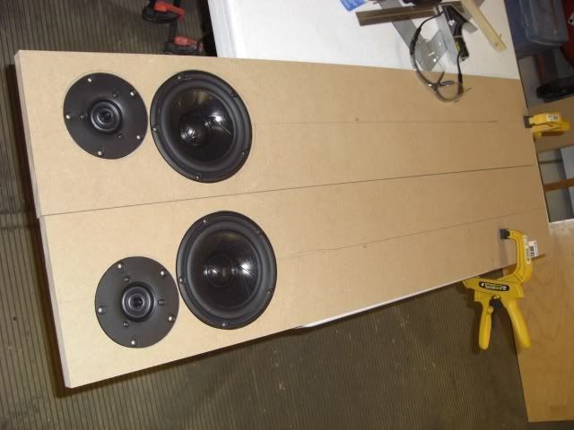
Last pics for a couple of weeks...wish i would have had time to get the rest of the pieces cut and glued
Back
Front inner baffle...bottom cutout is to make up for the volume of the xtra pieces i added to screw the removable back to.
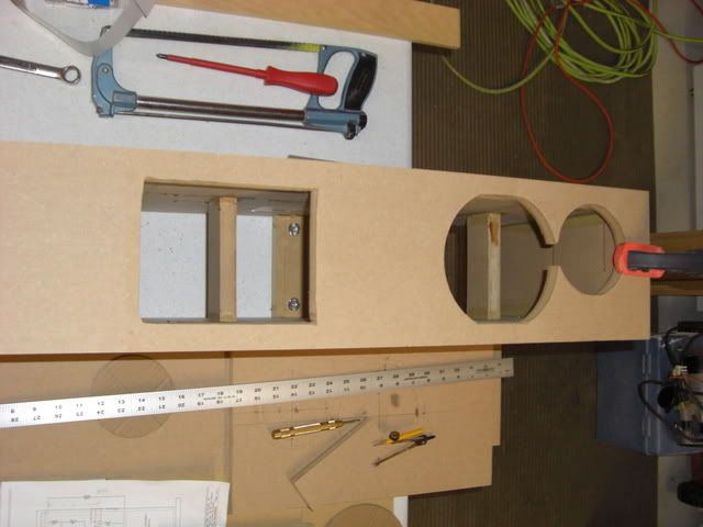
let me know if you see any problems....
Back
Front inner baffle...bottom cutout is to make up for the volume of the xtra pieces i added to screw the removable back to.
let me know if you see any problems....
I forgot to mention what I think is going to be my favorite new tool. Saw this on Zaphs Blog
Craftsman Multipurpose Router Guide
Sears item# 00925179000 Mfr. model# 25179
I did cut a couple of test driver recesses and they came out great!
I've never tried the jasper jig but I can't imagine that it could do a better job.
Sorry no pics of the recesses so you'll have to take my word...
 [/IMG]
Craftsman Multipurpose Router Guide
Sears item# 00925179000 Mfr. model# 25179
I did cut a couple of test driver recesses and they came out great!
I've never tried the jasper jig but I can't imagine that it could do a better job.
Sorry no pics of the recesses so you'll have to take my word...
I've made one out of a plastic breadboard that done 100's of driver and port holes but that thing is just so simple and clever with being adjustable.
R-Carpenter said:tizeye said:
May be you better off not doing it with the Craftsman router. They are a bit flimsy and ¾ round over is a big bit. There's a reason it has a ½ shaft and Craftsman doesn't have ½ collect. Then running a bit this size, don't even think of holding the piece in one hand and router in another. Clamp the hell out of it.
Sorry if I am pointing out the obvious.
I agree, but I didn't know what I was doing when shopping for a router. It was the one "new tool" that you always purchase as part of a DIY project, in this case an enterainment center. Now I have to make do with 1/4" shaft, non-plunging. But hey, it was on sale, a package special including table. If I knew then what I know now - skip the table and get the 1/2" drive plunging - which would have been about the same price. Problem now is thart routing is so infrequent that I can't justify a new/second router. That is why I was happy to find a 5/8 roundover bit on a 1/4 drive! Worked fine on MDF, haven't tried for solid hardwood. And yes, I do clamp before routing. Also, for "plunging" I pre-drill a start point if all the way through - like a speaker hole, and freehand groove from circle edge a start point for the circle jig when routing recessed circles.

- Status
- Not open for further replies.