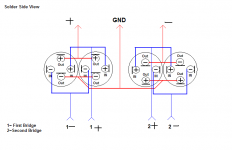
classd4sure said:Hi,
I still haven't tested this, still wiring. I can sure recommend not trying this P2P, some kind of fire/shock hazard!
I'm using 12AWG solide core.
Hi Chris
Nice diagram. 😀 That is the exact way that I thought you would be wiring them up. Whew ... 12awg solid wire will be a bit of a handful.
 I think that it will be worth it though? 😛 😱
Yes and don't want no kind of fire/shock hazard in the PS thankyou very much.


Look forward to hearing the results

Hi all,
I just noticed LC Audio website has been updated (sort of) recently.
It appears the release date for the 700XE is the 15th of December.....Damn its expensive though...
I just noticed LC Audio website has been updated (sort of) recently.
It appears the release date for the 700XE is the 15th of December.....Damn its expensive though...
Unfortuately,
I have been trying to contact lcaudio JP a number of times but there has been no replies...
I have been trying to contact lcaudio JP a number of times but there has been no replies...
ackcheng said:Unfortuately,
I have been trying to contact lcaudio JP a number of times but there has been no replies...
Hi ackcheng
Keep trying to contact them and let us know how long it takes to get in touch with them? ...
😕
 😡
😡Hi,
kLe // 4 poles are really something. With the lower impedance from them power is incredible and tightly controlled which makes it too revealing for most sources.
Cheers,
Chris
kLe // 4 poles are really something. With the lower impedance from them power is incredible and tightly controlled which makes it too revealing for most sources.
Cheers,
Chris
I really like the BHC T-Network caps, so, I will see if I can use these in this arrangement?
Well the V4P setup was originally designed in 1996 with the purpose of replacing real 4 pole caps, such as the T-Networks.
However KLe's idea of combining the two is not that far fetched.
T-Network caps in parallel will not give an intrinsic solution to simultanous charging and discharging, and thus may also suffer from current wobbling. In fact i cant see how you can device a solution with simultanous charging and discharging with T-Networks alone, not using the V4P circuit. So the V4P circuit is just as applicable to T-Networks as to normal caps.
Actually the two technologies combine nicely. There is a bit more wiring involved, but it shouldn't be a big problem.
If you want to hear the effects of current wobbling, it's very simple:
Take a setup of (almost) any amplifier using only single caps in the power supply. (One for plus and one for minus rails of course).
Make a good listening test.
Now add two more capacitors of about the same size and type in parallel with the existing caps.
Make a new listening test. You will now notice the midrange is hard and cold, and the soundstage has become blurry, compared to the first listening test.
See below:
Attachments
Lars Clausen said:
Well the V4P setup was originally designed in 1996 with the purpose of replacing real 4 pole caps, such as the T-Networks.
However KLe's idea of combining the two is not that far fetched.
T-Network caps in parallel will not give an intrinsic solution to simultanous charging and discharging, and thus may also suffer from current wobbling. In fact i cant see how you can device a solution with simultanous charging and discharging with T-Networks alone, not using the V4P circuit. So the V4P circuit is just as applicable to T-Networks as to normal caps.
Actually the two technologies combine nicely. There is a bit more wiring involved, but it shouldn't be a big problem.
See below:
Hi,
That looks like two resistors in series on either side of the foil, couldn't you do away with the one on the output ?
Regards,
Chris
No, it's about making one capacitor 'invisible' to the other cap, so to block charge transfer from one cap to another. But still allow charge flow to the amplifier and from the rectifier of course.
The moment you do away with the resistors on the output, you have no control over where the amplifier takes the most of it's power from.
The moment you do away with the resistors on the output, you have no control over where the amplifier takes the most of it's power from.
Lars Clausen said:No, it's about making one capacitor 'invisible' to the other cap, so to block charge transfer from one cap to another. But still allow charge flow to the amplifier and from the rectifier of course.
The moment you do away with the resistors on the output, you have no control over where the amplifier takes the most of it's power from.
Isn't the purpose of parralled caps to create lower impedance? Wouldn't the resistors increase resistance instead? What kind of value would be the balance?
soongsc: Maybe i can illustrate it by an analogy:
You are builing a car, and you want more power than the one engine can give you. ( = lower impedance).
So you put in two engines, and connect the drive shafts together.
Now you have more power, but now you have no control of the powerflow in the two engines. If one engine sparks a millisecond before the other, you have a huge amount of power flow from one engine to the other. None of the engines have optimal op conditions.
So in this case we have solved it by connecting the two drive shafts through a soft joint ( = the resistors) The power flow now only goes from the engines to the gearbox, and no power is transferred from one engine to the other. I think you can imagine in this imaginary analogy, that the engines now work smoothly together, to provide a clean driveforce.
In cars, one would use hard shaft connection but make the timeing such that two four cylinders would become effectively an 8 cylinder. Much more power effecient. I wonder how that would translate to a PS circuit.
Hello,
LArs, i finished my amplifier with 5 zap 2.3SE.

Now, I want to synchronize the five module with a ZP Sync Generator, but when i powered the ZP Sync with 32V, there is no signal on the output ... I think this module doesn't work.
Do you have an idea ? 😀
Best regards.
Sebastien
Edit:
In fact, this is the clock generator which is broken ( RAltron 16,9344Mhz). I try to supply it with 5V and there is no output signal...
Why 16,9344 MHz ?
LArs, i finished my amplifier with 5 zap 2.3SE.
Now, I want to synchronize the five module with a ZP Sync Generator, but when i powered the ZP Sync with 32V, there is no signal on the output ... I think this module doesn't work.
Do you have an idea ? 😀
Best regards.
Sebastien
Edit:
In fact, this is the clock generator which is broken ( RAltron 16,9344Mhz). I try to supply it with 5V and there is no output signal...
Why 16,9344 MHz ?
Hi Sebastien
I used 16.9344 MHz because it is a standard audio frequency. But for the ZAPpulse it's not strictly necessary to go with a multiple of 44.1 kHz. So you can also use 16.0000 MHz or alike.
Does your sync have the HC4060?
Best regards
Lars C
I used 16.9344 MHz because it is a standard audio frequency. But for the ZAPpulse it's not strictly necessary to go with a multiple of 44.1 kHz. So you can also use 16.0000 MHz or alike.
Does your sync have the HC4060?
Best regards
Lars C
soongsc said:In cars, one would use hard shaft connection but make the timeing such that two four cylinders would become effectively an 8 cylinder. Much more power effecient. I wonder how that would translate to a PS circuit.
That could translate to a PS circuit that uses a triple phase mains (using 3 transformers and 3 sets of bridge rectifiers) and would give you an enormous reduction in power supply ripple.
Best regards
Gertjan
classd4sure said:Hi,
kLe // 4 poles are really something. With the lower impedance from them power is incredible and tightly controlled which makes it too revealing for most sources.
Cheers,
Chris
Hey Chris
Are you enjoying the extra speed, dynamics, articulation, detail, bass ectension, etc, that this approach is providing? Sounds like it is both good and bad at the momment?

Sounds like you might need to try the 0.022uF rectifier caps. What do you think?
 I would suspect that because this is allowing the amp to be more revealing that controlling Noise becomes even more critical. 😱
 Do you think that the 4 pole PS caps have run in enough?
Lars Clausen said:Hi Sebastien
I used 16.9344 MHz because it is a standard audio frequency. But for the ZAPpulse it's not strictly necessary to go with a multiple of 44.1 kHz. So you can also use 16.0000 MHz or alike.
Does your sync have the HC4060?
Best regards
Lars C
Lars,
Yes i have the HC4060.
Is there a better method to synchronise the five 2.3SE than the ZP sync generator ?
What happens if the " ZP sync generator " break during the use of the amplifier ?
Best regards.
Sebastien
Hello Sebatien
If it breaks during operation, the only thing will happen is that is goes in un-sync'ed mode, and plays on like before.
You will probably not notice it.
It is better to bypass the HC4060, and feed the 16 mHz directly to the ZAPpulse module. This way you get a multiphase sync, where all the module srun at same frequency, but at skewed phases. This gives less noise.
Best regards
Lars
Lars Clausen said:Well the V4P setup was originally designed in 1996 with the purpose of replacing real 4 pole caps, such as the T-Networks.
However KLe's idea of combining the two is not that far fetched.
T-Network caps in parallel will not give an intrinsic solution to simultanous charging and discharging, and thus may also suffer from current wobbling. In fact i cant see how you can device a solution with simultanous charging and discharging with T-Networks alone, not using the V4P circuit. So the V4P circuit is just as applicable to T-Networks as to normal caps.
Actually the two technologies combine nicely. There is a bit more wiring involved, but it shouldn't be a big problem.
If you want to hear the effects of current wobbling, it's very simple:
Take a setup of (almost) any amplifier using only single caps in the power supply. (One for plus and one for minus rails of course).
Make a good listening test.
Now add two more capacitors of about the same size and type in parallel with the existing caps.
Make a new listening test. You will now notice the midrange is hard and cold, and the soundstage has become blurry, compared to the first listening test.
Hi Lars
Thankyou for describing that interesting way of parallelling T-Net caps. 😎 Would you suggest using 0R1 resistors, to maintain a low impedance or is the last cap govening the impedance of the PS? What size caps and resistors would you use? 😛
Lars, another question ... is the last PS cap needed?

Hi Chris: with the 4 poles in parallel do you notice the sound that Lars has discribed ... the midrange is hard and cold, and the soundstage is blurry ???
- Status
- Not open for further replies.
- Home
- Amplifiers
- Class D
- ZAPpulse 2.3SE vs. 700XE