Good day everyone
I purchased a couple Zapco 750.2s and a couple 350.2s. The 750s look like someone tried to resolder the transformers and was blind. I need to repar or replace them and don't know where to go. Help would be great. Also if anyone has schematics for these amps. Thanks
I purchased a couple Zapco 750.2s and a couple 350.2s. The 750s look like someone tried to resolder the transformers and was blind. I need to repar or replace them and don't know where to go. Help would be great. Also if anyone has schematics for these amps. Thanks
Last edited by a moderator:

I have posted three times on this forum and have never received one reply. Kinda feeling like I'm just not wanted here...lol
I hope you get everything sorted. If it were mine first thing clean off the mess someone made with solder, prep and organize wire cut off garbage bits and mark everything securely so no tags can drop off, then begin from there.
Nice to see Zapco is still going strong. I had some of their amplifiers when I was more involved with mobile stuff.
Pictures are always helpful but appreciated too, this place is packed full of gear heads who enjoy that stuff 😉
Nice to see Zapco is still going strong. I had some of their amplifiers when I was more involved with mobile stuff.
Pictures are always helpful but appreciated too, this place is packed full of gear heads who enjoy that stuff 😉
Last edited:
Your right picture would have been a good idea, I appreciate the input.
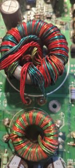
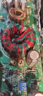
Here you go.
Looks like the inductor was resoldered on one as well. Still dirty also, I need to clean them up.

Here you go.
Looks like the inductor was resoldered on one as well. Still dirty also, I need to clean them up.
Attachments
It looks like he was using the Zap to practice his soldering technics. It will clean up with heat. Until you get tech help I would take care of that meantime, prep is 95%.
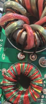
I managed to get the transformer off the board but I don't think its salvageable. Half the wires were just soldered together in a big clump on the top of the board with only solder running through the hole.

Last edited by a moderator:
It can be done but it all looks not that inviting to be honest.
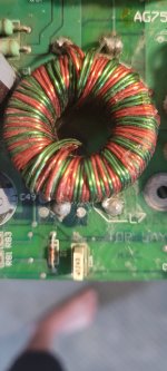
You could remove the enamel of the stranded wires of the coil and solder them nicely together. Then back to the board. Definitely use 60/40 solder and not lead free stuff.
You have not much to loose and you’ll improve skills regardless of the outcome.
You could remove the enamel of the stranded wires of the coil and solder them nicely together. Then back to the board. Definitely use 60/40 solder and not lead free stuff.
You have not much to loose and you’ll improve skills regardless of the outcome.
For future reference to remove something like this reliably requires cutting it off, then desoldering the stubs of wire from the PCB using the right desoldering bit for the job. The original soldering joints look cold and clearly weren't done with a large enough soldering iron or enough flux. You need to pre-tin the wires ends first with plenty of flux - the photo shows them untinned and oxidized...
Its all a sketchy manufacturing technique anyway, crimped terminals would be greatly preferred.
Its all a sketchy manufacturing technique anyway, crimped terminals would be greatly preferred.
- Home
- Amplifiers
- Power Supplies
- Zapco reference toroidal transformers