I'm confused because the board's silkscreen says 28V AC, not 12V etc. I'd like to use a 25V transformer, but then would I have to swap out that resistor for a lower value?
According to the schematic in hd220's thread the values are quite OK for your transformer.
The AC sense resistor is perfect for 25 V AC with 15k.
25 V AC give ~35 V DC after rectification and smoothing. According to fig. 6 in the datasheet the corresponding resistor should be 11k while it appears to be 15k. But if the PCB works with that value, leave it in. That way you have some more headroom for supply fluctutation.
The series resistor for the relays should be 470 Ohm. Apparently it is of that size although it appeared to be 270 Ohm in the photos, so no change there either.
Sorry, I thought it was the same as the board I used. It seems it is not. On my board you had the 28v ac on one side and 12v-0 dc on the other. Sorry to confuse
Even then you don't get 12 V DC from a simple 12 V transformer. You get 12 V AC from a 12 V transformer and if you add a rectifier and a smoothing cap, you get ~17 V DC.
Yes, well I didn't want to get into an argument. You can't just run it with 28v ac!!! You can take the 12v dc off your amp board supplying the op-amps, but it is a bad idea. You can just use a power supply for a phone or something as long as it is DC. Just pull it to bits. Or a trany, and a few diodes. 12v is not critical. Read hd220's thread. It is good. It will be useful. Regards Barry
You don't need a soft start board, that is the idea of sticking your ac from your transformer onto the board. It is 'speaker protection and soft start'
So the verdict is, a separate supply or let it be?
If I build another supply, does it have to be regulated DC and how much power does the transformer need to be able to put out? Are we talking 10mA or 1A?
Thanks.
If I build another supply, does it have to be regulated DC and how much power does the transformer need to be able to put out? Are we talking 10mA or 1A?
Thanks.
There's a thread on this speaker protection board that I started here:
http://www.diyaudio.com/forums/chip-amps/164061-speaker-protection-board-ebay.html
I traced and posted a schematic. There is some discussion that might be useful. I bought 4 of these boards all under $10 cdn, including shipping. Can't build it for that.
Cheers.
Missed your post. Very informative. But to make sure...
You need a separate transformer to run the board and it needs to be 32VDC (or whatever the Vcc input is silk screened as)?
I think on my board since the relays are 12V, I would use a 9V transformer and a diode bridge to give me ~12V. Does it have to be regulated? If so, then I would need a higher voltage transformer.
And you don't necessarily have to hook up the AC line? How does it work that there is only 1 AC input? I think my electronics theory is going down the drain...
Have a look at the datasheet in that other thread, and all your questions should be answered. Or, hang on for a couple of weeks 'till mine arrive...🙂
Have a look at the datasheet in that other thread, and all your questions should be answered. Or, hang on for a couple of weeks 'till mine arrive...🙂
Just ordered mine 2 days ago so I doubt they'll be here for a while.
For what it's worth, there is a new "YJ" version currently on ebay. It looks very similar with the layout changed to accommodate different form factor relays (I assume). Anyway, just as my schematic in the other thread ( http://www.diyaudio.com/forums/chip-amps/164061-speaker-protection-board-ebay.html ) shows, this one is not likely to vary from the upc1237 data sheet by much.
The link to the ebay listing: BTL Speaker protected board-yj on eBay.ca (item 190506327839 end time 05-Mar-11 10:32:16 EST)
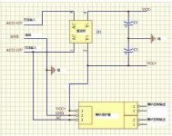
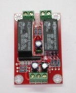
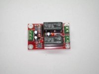
Below are 2 photos and (can you believe it!) a connection diagram! The connection diagram appears to concur with the both the discussion here and on the other thread.
TheLaw117 - I hope this helps you.
The link to the ebay listing: BTL Speaker protected board-yj on eBay.ca (item 190506327839 end time 05-Mar-11 10:32:16 EST)
Below are 2 photos and (can you believe it!) a connection diagram! The connection diagram appears to concur with the both the discussion here and on the other thread.
TheLaw117 - I hope this helps you.
Attachments
Last edited:
For what it's worth, there is a new "YJ" version currently on ebay. It looks very similar with the layout changed to accommodate different form factor relays (I assume). Anyway, just as my schematic in the other thread ( http://www.diyaudio.com/forums/chip-amps/164061-speaker-protection-board-ebay.html ) shows, this one is not likely to vary from the upc1237 data sheet by much.
The link to the ebay listing: BTL Speaker protected board-yj on eBay.ca (item 190506327839 end time 05-Mar-11 10:32:16 EST)
Below are 2 photos and (can you believe it!) a connection diagram! The connection diagram appears to concur with the both the discussion here and on the other thread.
TheLaw117 - I hope this helps you.
It does help! I see 32VAC going through a diode bridge and giving the Vcc. But then wouldn't that give the desired 12VDC. It would actually make somewhere around 45VDC where the relays are printed with 12V.
So should I be using a separate transformer for the Vcc? And I'm stil curious as to how much current it needs to operate and I am assuming from the diagram that it does NOT have to be regulated.
You make a good point regarding the 12vdc relays versus the bridge rectified AC that is independently questioned just now by prairiemystic in post # 18 in the http://www.diyaudio.com/forums/chip-amps/164061-speaker-protection-board-ebay-2.html thread.
So . . . the question is, do you add a second xfrmr or perhaps used a 3 pin 12 v regulator for the relay drive, or other solution?
So . . . the question is, do you add a second xfrmr or perhaps used a 3 pin 12 v regulator for the relay drive, or other solution?
Last edited:
From looking at various eBay versions, I think that the Vcc input has to be more on the lines of the operating voltage of the relay. I don't think it has to be spot on. I think they can run with a little bit more voltage than speced, but I think that diagram has to be wrong OR it is just a generalized diagram and excludes some other parts. So if they are 12V relays, you should be giving it maybe 12-18V, but surely not 45V.
I don't know how two relays in series work, but taking a WILD GUESS. 45V / 2 = 22.5V which is closer to the 12V spec...but that's guaranteed wrong.
Could be wrong but I think there is just a misprint of misinterpretation in there.
I don't know how two relays in series work, but taking a WILD GUESS. 45V / 2 = 22.5V which is closer to the 12V spec...but that's guaranteed wrong.
Could be wrong but I think there is just a misprint of misinterpretation in there.
Last edited:
A relay can take overvoltage limited by the package power dissipation.
For the Omron G2R family, max. 170% coil voltage up to 30C ambient (20.4V for 12V coil) http://www.omron.com/ecb/products/pdf/en-g2r.pdf
Most power amps have too high a DC rail voltage and I use a separate power transformer for the protection circuit. I have also wound a secondary on the main toroid for this.
The 12v does not need to be regulated and is low current. Any small supply. Like I said, A DC power supply for any small electronic device. Or a miniature 10v transformer and a couple of diodes. The other hole on the board is for one wire to one of your MAIN transformer out puts. You do NOT need an earth. It is just so the speaker board can sense the AC. It is really easy!!
Read and understand the datasheet. Read and understand posts #289, #296, #301. You need the AC voltage and the positive DC voltage from your amps power supply. A separate transformer with rectifier and smoothing cap is superfluous.
Or you do it like on the protection board under discussion and use a series resistor for the relay coil.
Most power amps have too high a DC rail voltage and I use a separate power transformer for the protection circuit. I have also wound a secondary on the main toroid for this.
Or you do it like on the protection board under discussion and use a series resistor for the relay coil.
I prefer a separate supply for the dc just to stop any imballance in the amp, but like pacificblue says, it is not neccessary. You do have 12v on that particular amp I believe for driving the op-amps. If i'm correct you will find it around one of the regulators in the middle of the board.
Another simple solution is to do as prairiemystic suggested with a winding around the outside of the toroid but I find it is messy and takes some time and fiddling to get the correct voltage.

- Status
- Not open for further replies.
- Home
- Amplifiers
- Chip Amps
- "Yuanjing" Gainclone 3886 - eBay amazing value ?