I'd suggest Monolith Magnetics in Belgium. They do custom stuff as of a few months ago at least. They have tech and design assistance.
Great to work with.
Great to work with.
50AE, you're very right with your statements. The drawbacks in this case are 1st the obviously badly designed original transfromer that needs to be replaced 2ndly with another one of identical footprint. I know that increasing the lamination stack height also will increase turns length, and that the best transformer MTL-wise would be the one on a circular core, and the best one with usual laminations (stamped from steel sheets) is the one with square iron cross section. But has the TO any choice at all to do so?
Best regards!
Best regards!

Kay, you're right as well. From personal experience I suspect the culprit was most probably a crossed turn that shorted with time.
If overheating was an issue as well, one could try heatsinking the transformer as well and giving better cooling.
As for tweaking the design, it's best to increase the stack height, yes, as MLT doesn't increase in the same proportion. For example a 2cm x 2 stack resulting into 4cm2 surface area has a starting MLT of 8cm. Bringing an additional 2cm stack ( 2x4 gives us double surface area (8cm2), but 1.5 times MLT (12cm).
Another thought - one could also redesign the transformer for C-cores GOSS, which he could run on higher flux density. There are standard GOSS substitutes for EI shapes. That should keep the same footprint.
yes, heat is always the primary consideration, that is why i will choose the core material, M6 GOSS 0.35mm thick and run at lower flux densities, 1T max.....
But your final judging parameter is not flux density, it is the resulting magnetizing current that results from the average core permeability. It's a fine balance between flux density and number of turns. Using too little flux density and your wire length will be higher, thus higher Rdc losses. Using too high flux density will result into saturation on voltage peaks region, giving lower primary inductance at these peaks, hence higher quiescent current. But you also simultaneously have lower primary Rdc, which inversely lowers the dissipated quiescent energy despite the higher current. Until core saturation starts to have exponential significance.
Giving flux density headroom is IMHO best left for DC flux density of the transformer from potential DC mains. Especially toroidal transformers, most having high permeability giving them the chance for lowest quiescent current, but as well high sensitivity to DC saturation.
Giving flux density headroom is IMHO best left for DC flux density of the transformer from potential DC mains. Especially toroidal transformers, most having high permeability giving them the chance for lowest quiescent current, but as well high sensitivity to DC saturation.
Thank you H713 🙂 I did send Heyboer an email just before Easter. I hope they can help. I keep hitting a dead end where no manufacture wants to create the PT.You may reach out to Heyboer transformers to see if they can help you. I don't believe they have a minimum order quantity, and last I talked to them (which was 4 - 5 years ago) their prices were pretty sane for what they do.
If you're dealing with a transformer that just doesn't have a big enough window for what needs to go in there, well, there's only so much anyone can do, and it's going to be labor-intensive.
Hello Extreme_Boky, if I hit a dead end I am thinking about using a second chassis just as you mentioned. I would be okay with that. Thank you very much for your thoughts.Contact Hubert... good luck.
View attachment 1046034
I'd consider an off-chassies power supply with 2, maybe even 3 transformers to replace that monster.... if everything else fails.
Here is this for a chuckle...I contacted Hammond who originally made the transformer and they recommended I go with 9 independent transformers to replace the one transformer. They said that would be too many transformers and not enough space on a secondary chassis. Well of course! I am not a designer but my gut feeling is that the primary shorted because it got too hot due to insufficient winding insulation that broke down?Hello Extreme_Boky, if I hit a dead end I am thinking about using a second chassis just as you mentioned. I would be okay with that. Thank you very much for your thoughts.
in some designs, an air gap between the primary and secondary coils is done so that there are no hot spots inside the primary coil windings..
With friends like that, who needs enemies? 😉Here is this for a chuckle...I contacted Hammond who originally made the transformer and they recommended I go with 9 independent transformers to replace the one transformer. They said that would be too many transformers and not enough space on a secondary chassis. Well of course! I am not a designer but my gut feeling is that the primary shorted because it got too hot due to insufficient winding insulation that broke down?
9 transformers is nonsense, and clearly replacing yours with a bunch of ready made off the shelf transformers ... and even so....
Worst case, and that making a similar looks chassis just for aesthetic reasons, two transformers (custom wound) would be more than enough: one carrying only the HV, other all the lower voltage windings.
Here is my suggestion, this is WAY more doable so transformer winders might look at this solution with slightly less awe/fear.
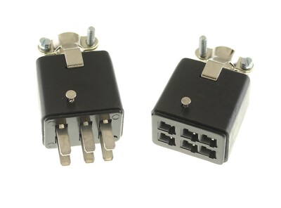
Make TWO transformers, same footprint as the original so one can be installed in the original chassis, in the original cutout, the second one in an extra chassis, preferably similar looking although that´s not a deal breaker, joined to main chassis using an industrial , Cinch Jones type connector.
Those are designed for heavy duty 380/440V motor applications, so this Audio use is a picnic for them.
Current transformer is 1060VA capable.
Well, not really, that´s why it fails.
Now if we split its job between two same original size but each is tasked with HALF the job, some 500-550VA each, it becomes doable and safe, since wire section can be almost doubled in all windings, primaries AND secondaries,
Here primaries failed first, my guess is because they live in the hard to ventilate core, but no doubt same compromise must have been taken in secondaries too.
I suggest mounting the low voltage high current transformer in original cutout because high current benefits from short fat wires, besides they are many so avoiding a zillion pin connector is a bonus.
HV only requires 6 wires/pins.
Being very high voltage, safety precautions apply:
Transformer side (active) connector must be female to avoid exposed HV on pins, amp side will be male, either chassis mounted or floating at the end of a short wire pack/umbilical, say 5 to 10 cm.
My split transformer suggestion:
I´d approach winders with this new request, which at least is physically doable , it breaks no Physics Laws he he.
Only "wild" request is that it uses same EI lamination size, so it fits in the original footprint.
At least the multitapped low voltage one.
JM, if you were close by I would hug you right now! Lol, that is exactly what I was hoping someone would say. I am going to use this recommendation moving forward. I have communicated with my technician as well and this is the route we will take. I don't have the heart to sell or give up this amp for adoption.With friends like that, who needs enemies? 😉
9 transformers is nonsense, and clearly replacing yours with a bunch of ready made off the shelf transformers ... and even so....
Worst case, and that making a similar looks chassis just for aesthetic reasons, two transformers (custom wound) would be more than enough: one carrying only the HV, other all the lower voltage windings.
Here is my suggestion, this is WAY more doable so transformer winders might look at this solution with slightly less awe/fear.
Make TWO transformers, same footprint as the original so one can be installed in the original chassis, in the original cutout, the second one in an extra chassis, preferably similar looking although that´s not a deal breaker, joined to main chassis using an industrial , Cinch Jones type connector.
Those are designed for heavy duty 380/440V motor applications, so this Audio use is a picnic for them.
Current transformer is 1060VA capable.
Well, not really, that´s why it fails.
Now if we split its job between two same original size but each is tasked with HALF the job, some 500-550VA each, it becomes doable and safe, since wire section can be almost doubled in all windings, primaries AND secondaries,
Here primaries failed first, my guess is because they live in the hard to ventilate core, but no doubt same compromise must have been taken in secondaries too.
I suggest mounting the low voltage high current transformer in original cutout because high current benefits from short fat wires, besides they are many so avoiding a zillion pin connector is a bonus.
HV only requires 6 wires/pins.
Being very high voltage, safety precautions apply:
Transformer side (active) connector must be female to avoid exposed HV on pins, amp side will be male, either chassis mounted or floating at the end of a short wire pack/umbilical, say 5 to 10 cm.
My split transformer suggestion:
View attachment 1046693
I´d approach winders with this new request, which at least is physically doable , it breaks no Physics Laws he he.
Only "wild" request is that it uses same EI lamination size, so it fits in the original footprint.
At least the multitapped low voltage one.
One other possible winding scheme that could work would be to move the 200 volt winding over to the HV trafo, and make that the look-alike drop in. Then make the low voltage high current one a toroid, and mount up under the main chassis in a base that looks similar to the amp chassis and physically attaches. Two or more locking Molex connectors (the .25” center, .093“ pin variety) to connect it INSIDE the composite chassis. An 800 VA core - not TOO much vertical space, cool running and plenty of winding window for all those fat wires.
Wg_ski, I can see this as a good alternative as well. It would look amazing actually. Very smart.One other possible winding scheme that could work would be to move the 200 volt winding over to the HV trafo, and make that the look-alike drop in. Then make the low voltage high current one a toroid, and mount up under the main chassis in a base that looks similar to the amp chassis and physically attaches. Two or more locking Molex connectors (the .25” center, .093“ pin variety) to connect it INSIDE the composite chassis. An 800 VA core - not TOO much vertical space, cool running and plenty of winding window for all those fat wires.
Wg_ski, I can see this as a good alternative as well. It would look amazing actually. Very smart.
I have been winding transformers Power and OPT for many years and I can wind the transformer you need, but there are two points:
1. I live in Israel and I need to check the possibility and cost of shipment.
2.What is the estimated cost of your transformer?

I have to calculate how much I will spend on components.
I am a private person, but if you want to order from a company, I can give you addresses, it will be 2-3 times more expensive in a company. In Israel, several large and small companies wind transformers for custom made.
Thank you bobikdartanan, thank you very kindly for your offer. I have found a manufacturer in the United States that can create a single transformer for me that another member mentioned I should try and that is Heyboer Transfomers out of Michigan.I have been winding transformers Power and OPT for many years and I can wind the transformer you need, but there are two points:
1. I live in Israel and I need to check the possibility and cost of shipment.
2.What is the estimated cost of your transformer?
View attachment 1047134
I have to calculate how much I will spend on components.
I am a private person, but if you want to order from a company, I can give you addresses, it will be 2-3 times more expensive in a company. In Israel, several large and small companies wind transformers for custom made.
I am also seriously considering the option that JMFahey and wg_ski recommended. I really like wg_ski's
H713, Arlyn at Heyboer Transformers in Michigan is able to help me out if I decide to go the one power transformer route. They can do a one off of this beast for I think a very reasonable price. I am very interested in wg_ski's recommendation on having a second chassis that sits underneath the main chassis. The lower chassis would house a toroidal transformer and the other transformer would sit in place of the old one. I think that would look terrific. It would end up costing more but I wouldn't mind that.Thank you H713 🙂 I did send Heyboer an email just before Easter. I hope they can help. I keep hitting a dead end where no manufacture wants to create the PT.
Hello everyone...I have decided to go the route of having one transformer to replace the original transformer whose primary failed. It's an updated design according to the designer of the 304tl power amplifier, so I am hopeful. The turnaround time for Heyboer Transformers out of Michigan said 5 weeks with another two weeks to receive it in Canada, then whenever my technician can get to it. I should have it up and running in about 3 months. I will let you know how it all goes then. I want to thank everyone who took the time to answer me...that was very considerate.
wg_ski...I still liked your idea of having a secondary chassis with a toroidal transformer but the designer felt I should stay true to his design. I will this time but I won't should there be a failure a second time 🙂 Total estimated cost will be about $1,300 CAD to replace the original transfomer.
wg_ski...I still liked your idea of having a secondary chassis with a toroidal transformer but the designer felt I should stay true to his design. I will this time but I won't should there be a failure a second time 🙂 Total estimated cost will be about $1,300 CAD to replace the original transfomer.
Hello again H713...I just wanted to let you know Arlyn at Heyboer Transformers will be creating a new transformer as a replacement for the transformer that failed. They didn't balk at creating it for me...just they could and that was that. I can't tell you how many dead ends I hit trying to get someone to create it for me. Thank you for the great advice!You may reach out to Heyboer transformers to see if they can help you. I don't believe they have a minimum order quantity, and last I talked to them (which was 4 - 5 years ago) their prices were pretty sane for what they do.
If you're dealing with a transformer that just doesn't have a big enough window for what needs to go in there, well, there's only so much anyone can do, and it's going to be labor-intensive.
- Home
- Amplifiers
- Power Supplies
- Your thoughts on a custom power transformer...