Hello everyone! I hope you can offer some advice?
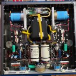
I purchased a custom power amplifier from an older gentleman who designed a Class A stereo power amplifier based on the 304TL transmitter tube. The primary winding of the custom Hammond transformer shorted after several years. I spoke to the designer of the amp and he made some modifications for an updated transformer to replace the tranny that shorted with some better specs that can be dropped into place replacing the defective one (diagram attached).
I live in Canada and Hammond doesn't do one off's any more. I called another company called Electronics Craftsman in Ontario and same issue where they don't do one offs and require a minimum of 6 (Hammond requires a minimum of 10). I contacted Edcor in California and they said they cannot help. I know that maybe supplies are difficult to come by and many smaller companies might have gone out of business due to the pandemic? If anyone has any suggestions for me I would surely appreciate your thoughts and advice? The amp is only several years old and the older gentleman created something quite special here. More importantly the sound is wonderful and I have some great synergy happening within my system.
As a last resort, I may have to break down this transformer into smaller transformers and create a separate power supply unit and connect the two units through a cable.
I can't send it back to him for servicing as it was crated and shipped to me and we are several thousand miles apart. He lives in Calgary, Alberta on the West Coast and I live in Nova Scotia on the East Coast.
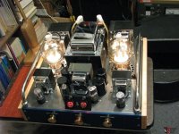
I have attached some files that will be of some use to you. This is a big transformer! The amp is beautifully crafted.
I purchased a custom power amplifier from an older gentleman who designed a Class A stereo power amplifier based on the 304TL transmitter tube. The primary winding of the custom Hammond transformer shorted after several years. I spoke to the designer of the amp and he made some modifications for an updated transformer to replace the tranny that shorted with some better specs that can be dropped into place replacing the defective one (diagram attached).
I live in Canada and Hammond doesn't do one off's any more. I called another company called Electronics Craftsman in Ontario and same issue where they don't do one offs and require a minimum of 6 (Hammond requires a minimum of 10). I contacted Edcor in California and they said they cannot help. I know that maybe supplies are difficult to come by and many smaller companies might have gone out of business due to the pandemic? If anyone has any suggestions for me I would surely appreciate your thoughts and advice? The amp is only several years old and the older gentleman created something quite special here. More importantly the sound is wonderful and I have some great synergy happening within my system.
As a last resort, I may have to break down this transformer into smaller transformers and create a separate power supply unit and connect the two units through a cable.
I can't send it back to him for servicing as it was crated and shipped to me and we are several thousand miles apart. He lives in Calgary, Alberta on the West Coast and I live in Nova Scotia on the East Coast.
I have attached some files that will be of some use to you. This is a big transformer! The amp is beautifully crafted.
Attachments
Last edited:
single ended power traffos are about six times the weight of the traffo used for push pull for a lot less power output..
this is because class A amps draw constant power from the moment you power up your amp...
you traffo is 2 1/4 x 4 inches and weighs in at around 50 lbs,,,
power handling of the core is around 2500 volt amperes, secondary power available is around 1500 watts, maybe you have more than what you need..
this is because class A amps draw constant power from the moment you power up your amp...
you traffo is 2 1/4 x 4 inches and weighs in at around 50 lbs,,,
power handling of the core is around 2500 volt amperes, secondary power available is around 1500 watts, maybe you have more than what you need..
Hi Tony, thank you for your reply…I am not much of a technical person. I understand many things but when it comes to design I have difficulty. I am hoping someone might be aware of a custom transformer company who might do a one off using the new tranny design that was provided to me?
The gentleman who designed and manufactured the amp indicated it outputs about 30 watts in Class A. Those 304TL output tubes become extremely hot and the plate voltage is at 960 volts. I installed an updated 20 amp line to my electrical panel just for this amp.
Bill
The gentleman who designed and manufactured the amp indicated it outputs about 30 watts in Class A. Those 304TL output tubes become extremely hot and the plate voltage is at 960 volts. I installed an updated 20 amp line to my electrical panel just for this amp.
Bill

Hey Bill, i design and build power traffos used in my amplifiers, although i am not a commercial winder...
from your pdf files and given your core area i can do a calculation of your power traffo windings, although i am not sure how that may help you as we live thousands of miles apart...
as to how your traffo primary burned out, i suspect that it used a smaller gauge wire, 2500va/120 vac is 20A....requires a awg #10 magnet wire, if i were to do that...for that size wire, i would use double cotton covered enamel wire...
Last edited:
Hello Tony, thanks so much for your time in replying. I can't speak from the design side of the transformer but originally it would have been Hammond in Canada who designed and manufactured the transformer based on the requirements provided from the designer in Calgary, Alberta. (According to the designer of the amp he mentions that he ordered two of these power transformers back round 2009. The other one failed as well. It was used in a stereo Class A amp based on the 845 output tube. But this transformer failed much earlier on.)
The problem is who can manufacture the transformer for me and not require a minimum order. I could pay for two in case I need a backup but 6 or 10 wouldn't make financial sense for me.
I like your idea of a larger gauge wire and beefed up insulation between windings but that would mean a larger footprint for the transformer likely? I wonder if it would then fit into the space that was allotted in the original amp design. Your design and thoughts are very considerate and cautious...I like that.
As a last resort I was going to try having it manufactured in China but I worry about quality control. Tony, do you get your transformers wound in the Philippines? I would imagine you do?
Attachments
Hi Bill, i design and build my own, but i do not sell traffos, you have to buy my amps...
the Hammond traffo with2.25 x 4 inches seems to be more than enough for your amp....
but i will have to recalculate that....
if i were to redesign that traffo, i will do it without the center tapped winding. you gain about 30% more utilization for a cooler running traffo....
i would even redesign the psu to use the full wave voltage doublers, you save one winding coils and the traffo will even be more winder friendly.....
Last edited:
HI Wgs57,
your hint on the other alreadily failed xformer that was designed by the same person appears to verify Tony's assumption: There was something wrong in the design. You'd first have to look at why the primary winding did burn (wich is rather unusual), then have the replacement manufactured. I agree with Tony's assumption that the primary wire's cross section may have been way too small. Think of the constant load a PT has to feed into a class A amplifier.
What's the mains frequency where you live? Maybe it' 50 Hz, and the transformer was designed for 60 Hz?
Instead of a single primary of rather thick wire for 20 A, I'd suggest two windings, 120 Vac each, half the amperage, half the wire cross section. So you also could move to another part of the world, if you wish 😛.
Best regards!
Hello Kay, Tony...the line frequency in Canada is 60hz. The transformer, I think, was designed by someone in the know as he was near 70 when he built this amp and had worked in the industry all his working life. He would have supplied the specs to Hammond Manufacturing and they would have designed the transformer for his needs and Hammond would have known it was single ended as well amplifier as well. The designer (his name is Kruno and Croatian living in Canada) changed his requirements on the primary end. I sent Hammond the new requirement and they wanted me to break this one PT down into 9 PT's. Imagine creating a power supply with 9 transformers on a chassis? Lol, it would be ridiculous.
My problem so far has been not being able to get anyone to make a new PT for me in North America, although I haven't looked into many manufacturers in the USA yet. Either they don't want to take it on, or they are too busy or there is a shortage of iron. When some manufacturers say no to me they don't want to tell me why they won't take it on, or they don't do one-offs...I have to order multiples to make it worthwhile for them. I live in North America (Canada). I don't mind getting someone to redesign another transformer for me but who would I get to make it? I think I would still be blocked. Tony Tecson manufactures his own PT's for his amplifiers. Who could you recommend in the Philippines who would manufacture one for me in your country?
My problem so far has been not being able to get anyone to make a new PT for me in North America, although I haven't looked into many manufacturers in the USA yet. Either they don't want to take it on, or they are too busy or there is a shortage of iron. When some manufacturers say no to me they don't want to tell me why they won't take it on, or they don't do one-offs...I have to order multiples to make it worthwhile for them. I live in North America (Canada). I don't mind getting someone to redesign another transformer for me but who would I get to make it? I think I would still be blocked. Tony Tecson manufactures his own PT's for his amplifiers. Who could you recommend in the Philippines who would manufacture one for me in your country?
perhaps JMFahey in south America may be able to help you. i can make traffos but to ship to America, that would be a killer....too much hazzle for me too...
do you have an as built schematics we can look at...?
did you try to ask? https://www.facebook.com/heyboertransformers/
or Chris Merren? http://www.merrenaudio.com/
do you have an as built schematics we can look at...?
did you try to ask? https://www.facebook.com/heyboertransformers/
or Chris Merren? http://www.merrenaudio.com/
Thanks for the confidence vote, I was already intrigued by this beast of a PT for a BEAUTIFUL amp which certainly must sound as good as it looks.
Sorry I can´t help you with this one, too large and complex for me plus the expensive shipping >25kg through DHL or similar BUT if worried about quality and not trusting China, here at DIY Audio some Polish Transformer winders are often mentioned, certainly somebody will offer name so as to find them, maybe even some contact data, who are known for good quality and reasonable prices.
Shipping from EU won´t be more expensive than from Philippines or South America and maybe significantly less.
Mind you, not dissing China at all, I am certain there are at least a couple "good" winders there ... the problem is finding who is who, a nice Net page tells us nothing.
Already making some back-of-an-envelope calculations from your first hand drawing, my estimation was some 1950VA, actually very close to Tony´s 🙂 , let me calculate a safe primary wire diameter.
2000VA/120VAC=17A (always round UP to next highest value)
Standard current density is 3A/mm^2 if you are short of space/funds but given a Class A amp (even worse, a TUBE one) is a HEAVY CONTINUOUS load, it would be safer to design for 2A/mm^2
So S(ection) would be 17A/2 A/mm^2=8.5 mm^2
From an AWG wire table:
* AWG10=6 mm^2 which meets the 3A/mm^2 "standard/commercial" spec
* AWG8= 10mm^2 which is "bombproof" .... problem is: will it fit available window space?????
That is always a big bottleneck in transformer design; to boot you can not go to a larger lamination because of the way the amp is built, it is literally "surrounded" AND it´s side-mounted so it must fit in the already existing hole.
I like and trust Hammond but I vaguely suspect all that bunch of secondaries was squeezed inside available space, so "minimum/barely enough" diameter wire was used.
Primary suffers most because it´s typically the first winding, and is surrounded by all others, so it heats up most.
STOP THE PRESS, WILL HAVE TO RECALCULATE, HAND DRAWING AND PICTURE DO NOT MATCH.
Too sleepy now, early morning here, will repeat later, BUT as an advance: hand drawing shows a horizontal outside mounted PT, "TOP" is a laminations pack with visible sideways windings, but pictures show actual top is one winding end visible, surrounded by iron, other winding end is inside chassis.
So relevant dimensions are different.
Oh well.
Hi JM! Fahey is a well known Nova Scotia name and you are in Buenos Aires...that is quite exciting! Very nice communicating with you and Tony. The designer of the 304TL amp is originally from Croatia and he is really a lovely older and well versed technical person. I asked him where he gets his designs from and he said "his head", LOL. I am sure he has looked into past schematics online, but he said he follows the specifications for the different tubes and he puts together everything, including punching the chassis. He wanted to design this Class A amp to prove that he could do it for much less than what these amplifiers may sell for today. He said he built it for about $5,000 CAD and I bought it for about $3,400 CAD. When I first saw it I went wow!!! What is this? I spoke to Kruno and he said he didn't want to ship it. I convinced him that I would have have it professionally crated and shipped and he agreed. This is not my first tube power amplifier and I fell in love with it. The PT did get hot to the touch after an hour or two but I assumed that would be normal. When the amplifier did fail it simply blew a fuse and then I reached out to Kruno to have him help me troubleshoot the amp. I followed his instructions and the amp was still blowing fuses. I then brought it to my technician and he felt likely the primary shorted. He removed the PT at my request because this amp with the PT installed is so heavy! The tech is waiting to hear back from me as to what my next steps are. Hammond has been no help unfortunately.
So you know, the photo of the transformer label is of the original transformer that failed. The drawing is the recommended new design from Kruno.
I have attached a copy of the schematic of the amp but I worry it may not be the finished schematic because the technician who was helping me had trouble matching the schematic with the layout. It is the only one I have though. The attachment has the old PT and the updated PT design from Kruno.
Attachments
Oh, how sophisticated 😳! This schematic may well have been designed so about a century ago.
I think JMF was right in his assumptions: Due to the sheer number of secondaries tons of insulation material was required, which consumes a big part of the winding window. Hence, the designer decided to decrease the wire diameters instead of opting for a bigger core 🙄.
Best regards!
I think JMF was right in his assumptions: Due to the sheer number of secondaries tons of insulation material was required, which consumes a big part of the winding window. Hence, the designer decided to decrease the wire diameters instead of opting for a bigger core 🙄.
Best regards!
i based my calculations on the RDH4 chapter 5..... design is for a 500 circular mils per ampere current density and if space allows, 700cm per ampere....
yes the available winding window is the show stopper...
if i were to redesign the psu, i will get rid of the full wave center taped scheme and go for a graetz rectifier... https://www.diyaudio.com/community/...r-with-transformer-without-center-tap.195614/
yes the available winding window is the show stopper...
if i were to redesign the psu, i will get rid of the full wave center taped scheme and go for a graetz rectifier... https://www.diyaudio.com/community/...r-with-transformer-without-center-tap.195614/
Ok, back to the race track.
Only I prefer to work Metric because it´s somewhat simpler/straightforward, if anything because all scales are "powers of ten" and convert to AWG only at the end, so wire supplier knows what I´m talking about if that´s how he has his bobbins labelled.
Although IF those mythical Polish winders are found, THEY will also use Metric, he he.
Chinese/Japanese/Korean too.
In any case, you will not give then a strict blueprint, let them design all by themselves and then ask them, before winding, what size primary wire they chose.
You have a legitimate interest in knowing that specific data, given that TWO transformers, and from a respected builder which of course they must know, failed the same way exactly there.
Pity you don´t know actual wire size used at your primary, so as to establish a "floor" as to what is NOT enough.
One detail: in the 40´s wire was expensive , transformers were complicated, lots of windings, so their compromise was in general to reduce wire diameter to minimum acceptable which still worked.
As a winder, I am often surprised at the highish DCR I find in old transformers, both in those I repair but also when indicated in certain schematics (such as Sears/Silvertone, Sams Photofacts, Bogen, etc.).
Only centertapped "full wave" HV rectifiers were possible, which are inefficient compared to single winding bridge rectified here it´s worse because we have two separate 5V windings (both centertapped), two 6.3V, centertapped, FOUR 10V 6A for power tubes, plus a 24V one, of course also centertapped.
Add to that the (sensible) 3kV Hi Pot testing all over the place.
Almost forgot the 4 wires for primary,
So we have 31 wires total 😱
A winding nightmare , no doubt Hammond won´t touch it with a 10 ft pole, the polite way to keep you away is to ask for a 10 unit minimum which they know is a deal breaker.
Ok, doubt thicker wire fits in or they would have used it already, so we might simplify it a little, still keeping it faithful to original spirit/sound.
CAVEAT: my former (and future) mains primary calculations apply to a single 120V winding just to save 2 wires and some insulation, of course if dual voltage is needed, two windings can be used, each half section (so 0.7X diameter).
Ok, enough for now, later will continue with calculations to suggest primary wire specs, full design is beyond a Forum answer, and to boot needs to know many practical details, such as actual EI lamination used (to have exact window dimensions), actual wires available (enamel thickness plays a role too), available paper/pressphan/nomex/mylar specs (insulation, thickness) since as mentioned above , insulation occupies significant space.
For mounting reasons, and the way transformer is mounted, lamination will need to be exact same so it can drop in in same chassis cutout and use same bolt holes, only possible variation (which I guess will be needed) is to stack laminations even higher, that directly reduces turns needed (more core area available) so you can fit slightly thicker wire in same window space.
Ok, back later.
Meanwhile search for those Polish winders (search in this very Forum) .
Not "Toroydii" (I bet I am butchering their name 🙂 ) but some others.
Or anywhere else in the World, of course.
Even China, why not?
Perfect! Straight from a VERY respected source.i based my calculations on the RDH4 chapter 5..... design is for a 500 circular mils per ampere current density and if space allows, 700cm per ampere....
Only I prefer to work Metric because it´s somewhat simpler/straightforward, if anything because all scales are "powers of ten" and convert to AWG only at the end, so wire supplier knows what I´m talking about if that´s how he has his bobbins labelled.
Although IF those mythical Polish winders are found, THEY will also use Metric, he he.
Chinese/Japanese/Korean too.
In any case, you will not give then a strict blueprint, let them design all by themselves and then ask them, before winding, what size primary wire they chose.
You have a legitimate interest in knowing that specific data, given that TWO transformers, and from a respected builder which of course they must know, failed the same way exactly there.
Pity you don´t know actual wire size used at your primary, so as to establish a "floor" as to what is NOT enough.
One detail: in the 40´s wire was expensive , transformers were complicated, lots of windings, so their compromise was in general to reduce wire diameter to minimum acceptable which still worked.
As a winder, I am often surprised at the highish DCR I find in old transformers, both in those I repair but also when indicated in certain schematics (such as Sears/Silvertone, Sams Photofacts, Bogen, etc.).
Only centertapped "full wave" HV rectifiers were possible, which are inefficient compared to single winding bridge rectified here it´s worse because we have two separate 5V windings (both centertapped), two 6.3V, centertapped, FOUR 10V 6A for power tubes, plus a 24V one, of course also centertapped.
Add to that the (sensible) 3kV Hi Pot testing all over the place.
Almost forgot the 4 wires for primary,
So we have 31 wires total 😱
A winding nightmare , no doubt Hammond won´t touch it with a 10 ft pole, the polite way to keep you away is to ask for a 10 unit minimum which they know is a deal breaker.
Ok, doubt thicker wire fits in or they would have used it already, so we might simplify it a little, still keeping it faithful to original spirit/sound.
CAVEAT: my former (and future) mains primary calculations apply to a single 120V winding just to save 2 wires and some insulation, of course if dual voltage is needed, two windings can be used, each half section (so 0.7X diameter).
Ok, enough for now, later will continue with calculations to suggest primary wire specs, full design is beyond a Forum answer, and to boot needs to know many practical details, such as actual EI lamination used (to have exact window dimensions), actual wires available (enamel thickness plays a role too), available paper/pressphan/nomex/mylar specs (insulation, thickness) since as mentioned above , insulation occupies significant space.
For mounting reasons, and the way transformer is mounted, lamination will need to be exact same so it can drop in in same chassis cutout and use same bolt holes, only possible variation (which I guess will be needed) is to stack laminations even higher, that directly reduces turns needed (more core area available) so you can fit slightly thicker wire in same window space.
Ok, back later.
Meanwhile search for those Polish winders (search in this very Forum) .
Not "Toroydii" (I bet I am butchering their name 🙂 ) but some others.
Or anywhere else in the World, of course.
Even China, why not?
a lot of tube power traffos coming from the states had always had two primaries of 115volt each, so that it is easy to convert to 230v is just a matter of series connecting them...i converted a lot of tube amps to our local voltage of 230volts that way.....
but what intrigued me in this case was the burned out primary winding, it would be nice to do a post mortem to find out what exactly happened...and yeas finding out the primary wire size can give clues...
Hey Bill, if you can ask Hammond what grade of steel they used, M6 goss being the best all around quality and M54 noss being low quality...
10 unit being asked by Hammond is their engineering evaluation of what production run would make sensible returns...
..
Yes, the burned primary was my concern also in #7, as in a class A amplifier any winding has to cope with the maximum current all the time. It's somewhat puzzling. Anyway, the solution might be that due to thermal reasons for the inner winding amperage per wire cross section needs to be lower, whicht might not have been accounted to.
Best regards!
Best regards!
You may reach out to Heyboer transformers to see if they can help you. I don't believe they have a minimum order quantity, and last I talked to them (which was 4 - 5 years ago) their prices were pretty sane for what they do.
If you're dealing with a transformer that just doesn't have a big enough window for what needs to go in there, well, there's only so much anyone can do, and it's going to be labor-intensive.
If you're dealing with a transformer that just doesn't have a big enough window for what needs to go in there, well, there's only so much anyone can do, and it's going to be labor-intensive.
Yes, given the strict size and footprint limitations, that is the only possible way to make window space "stretch" a little.
And in general, just thinking aloud, all other wire sizes "could" be left the same, BUT primary should be at least "next thicker" AWG size.
Which of course requires a larger window (next to impossible) o higher stacking to reduce number of turns needed.
And in general, just thinking aloud, all other wire sizes "could" be left the same, BUT primary should be at least "next thicker" AWG size.
Which of course requires a larger window (next to impossible) o higher stacking to reduce number of turns needed.
Designing a power transformer is not just simply picking current density values from tables.
First one needs to know the cooling rating to the power transformer compared to its MAXIMUM permissible heat dissipation in Watts first. That will primarily determine your VA rating.
Then one chooses a core, flux density and calculates the Rdc losses, which contribute to the most transformer heating. Rdc losses are calculated by determining the Mean Turn Length (MLT) of the coil, number of turns and wire gauge. Biggers cores will result in less turns per volt, but more MLT.
One also needs to take into account the magnetizing current, dependent of the core flux density (resulting in average permeability). That gives the quiescent current on the primary, where power is also being dissipated dependent of its Rdc
In the end, designing a custom power transformer with a quality to outlive your grandchildren (no crossed turns, cool and noise-free operation) is not easier and less time consuming than designing an output transformer.
Last edited:
- Home
- Amplifiers
- Power Supplies
- Your thoughts on a custom power transformer...