I have a manley 250 amp. Uses 10 el34's in output stage. individual trim bias, and a master bias supply adjustment. All tubes check out and are matched (by me on a calibrated Mercury 2000 and bias probe). Amp has a soft start feature that warms up the circuits using about 10% power. Problem is that tube number 5 goes into over bias condition then the HT voltage fuse blows. In soft start mode, #5 runs at about .200MV where it should be around .065MV as it used to do and the other tubes still do. If I put the amp in operate mode, full power, the bias for #5 climbs till the HT fuse blows. Tube test fine. Moving tubes to a second amp does not move the problem. question is if the 33ohm resistor indicated in the bias circuit burned out to an open condition, would it cause this. I don't think it's the individual trim bias since in softsart mode, the bias trim range does alter the bias for #5. But it's basically a few hundred MV off. If I pull tube #5 and it's partner tube #10, the amp runs fine, bias is good for all remaining 8 tubes, fuses do not pop. Again, the tubes are fine. I have plent of new tubes to use to diagnose, as well as being able to test #5 and have tube #5 perform normal in my second Manley amp. I'm attaching the bias area of the schematic. Over the week end I'll pull the amp out of the rack, and test the individual components in the circuit of tube #5.
Attachments
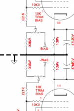
I'd suspect the coupling capacitor for tube #5, but it could also be one of the other components in the grid circuit. Remove tube #5 and one tube from the other PP phase (tube #1 ?) to maintain dc balance in the output stage and do some measurements - I think you see that the grid bias is off on that one particular position.. Now you just need to figure out why - do you have a full schematic?
ok, problem solved. 10 ohm resistor to pin 1/8 is open. everything else in the amp test just fine. I think I have one, if not, off to radio shack.
Hopefully it is that simple, but I bet it isn't. Since the B+ fuse blew how likely is it that this cathode current sampling resistor opened up due to excessive cathode current? (Answer: Very) I'd replace the 47uF cap across the cathode resistor as it may have been over-voltaged when the cathode resistor opened up.
Did you measure the voltage on pin #5 of tube #5 with the amplifier in operating mode? (Carefully of course)
Did you measure the voltage on pin #5 of tube #5 with the amplifier in operating mode? (Carefully of course)
Ok, good idea. done. cap changed. replaced the 10 ohm resister, rebiased, and we're in like flint. the resister is not even warm. the bias behavior is normal. thanks for the feed back.
Ok, good idea. done. cap changed. replaced the 10 ohm resister, rebiased, and we're in like flint. the resister is not even warm. the bias behavior is normal. thanks for the feed back.
Well this is great news.. Dodged a bullet I think.. Still I wonder what caused that resistor to fail, and would suspect an intermittent short or internal arc in that particular power tube - so even though it seems to be OK now I'd probably replace it to be sure.. Were it just the resistor that failed quietly I wouldn't expect the B+ fuse to have blown as that just removed a current path, and no place for that fault current to flow except through the bypass cap - which is usually very obvious because once significantly over-voltaged the cap will breakdown, overheat and usually explode... (Fuse probably prevented that scenario) 😀
- Status
- Not open for further replies.
- Home
- Amplifiers
- Tubes / Valves
- your opinion of this bias problem