carlmart said:
Building my own with a part that is SSOP-sized and with 28-pins? Certainly not!
But what is that AD say about grounding that should be ignored?
Carlos
Some designers sprinkle ferrite beads across a design with the wish that they do some good.
Also they might use the ferrite bead just to seperate the naming of the AGND and DGND in the schematic and netlist to keep them seperated in the PCB layout. An excuse for laziness instead of careful PCB layout.
SSOP soldering not as hard as it looks. Dont use too much solder and use copper-braid solder wick to clean up the excess.
rossl said:
Some designers sprinkle ferrite beads across a design with the wish that they do some good.
Also they might use the ferrite bead just to seperate the naming of the AGND and DGND in the schematic and netlist to keep them seperated in the PCB layout. An excuse for laziness instead of careful PCB layout.
SSOP soldering not as hard as it looks. Dont use too much solder and use copper-braid solder wick to clean up the excess.
Hi
I agree on the ferrite bead between "analog and digital ground", obviously that ferrite should be banned so both grounds become one (equipotential) plane.
Ferrites in supply lines however do their job, assumed applied correctly, that is, in line with oter measures.
One can hear and measure the effects.
best
abidr said:Heres the SPDIF DAC, please suggest any improvements if u can as layouts are still being done by a very good and nice friend.
Hi
I'd suggest to
- Use the inverter connected to pins 5 and 6
- Add series resistors in all data and clock lines
- Create space for bigger parts in the 8412 PLL filter network
- Reclock pin CS8412 pin 12 with pin 19
best
Hi Jim,This is the only DAC I ever built. I like the way it works.
Looks great..did I see correctly that USB is a possibility? How about I2S?
Regards,
Bas
did I see correctly that USB is a possibility? How about I2S?
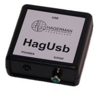
The HagDac daughter card shown above takes only S/PDIF input. The Chime motherboard has a USB input. Works fine. I can play CD from either my laptop or CD transport. But you have to be careful what you use for media software, those digital volume controls can re-calculate bits and take away from the sonics. Windows media player seems to be ok with volume at 100%.
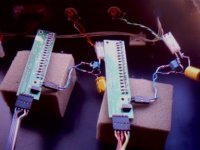
I would think the USB input is going to be bigger in near future, with many folks moving to hard drive storage. I doubt I will get into it for awhile, but other will. In fact, I'm making the USB circuit on a separate board; a standalone USB -> S/PDIF converter. Comes with a free headphone output too. Had actually cancelled the project, but received a lot of email requests to continue. Here's a shot of the prototype:
jh🙂
Add series resistors in all data and clock lines
You got that right! This is one of the best improvements you can make, as it helps to limit current transient spikes during transistor switching. Hardly anybody gets this (I'm glad to see you do!). Only schematic I've ever seen online with them was the one you posted above.
Some of these little things may not seem obvious. One has to spend a lot of time following the current paths of a circuit, inside the chips, too. The parasitic inductances and capacitances make all the difference.
In HAGDAC, I took it a step further and added a series inductor with the resistor. Resistor has to be both large and small. The larger the value, the less interruptive the current spike. However, you need a small value to minimize risetimes. I set resistance value for a desired risetime (in this case about 5ns). The parasitic capacitance of the short PCB traces and from input transistors of the receiving chip determine the RC time constant. I then ring this with the inductor. This has two benefits, it improves risetime by a factor of 1.6, and creates a second order filter, which reduces noise and other crap on the signal. Remember, any noise you see on the flats, is also present during the edges, and ends up adding jitter. A clean slow transition is way better than a noisy fast one. The value of the inductor should be approximately:
L = R*R*C/2;
Usually you just have to experiment, as the capacitance is unknown. I find it typically to be in the 5pF to 10pF range, unless the trace is long. It also helps to have a special (expensive) 1pF scope probe and a really fast scope.
BTW, on the HAGDAC, I did this for every single digital line, not just the clocks. Wish I had a photo handy, as the waveforms are texbook perfect. No noise visible with perfect edges. They look like computer simulations.
jh🙂
hagtech said:
You got that right! This is one of the best improvements you can make, as it helps to limit current transient spikes during transistor switching. Hardly anybody gets this (I'm glad to see you do!). Only schematic I've ever seen online with them was the one you posted above.
jh🙂
Hi Jim
I saw it, but that doesn't count 🙂 We included resistors long ago in our DAC design, and ever since then.....
Will look at thr RL combo, interesting.
Wit respect to the noise: Yes, it helps for the RF part. The LF noise should be handled differently.
cheers
That is an interesting approach, Jim, as the inductance will further limit the peak current on transistions. But I am not sure I would advise it for the noobs. You will definetly need to tweak the value to keep the rise time from becoming too slow.
Jocko
Jocko
My own creation... The Discrete
1) Discrete DAC revs. 1, 2 and 4 (or perhaps that should be Discreet for the latest iteration)... don't make me choose... they all have their own character.
2) Discrete DAC
3) Pros - Complete control from the CD source data to the analogue output, remarkable ability to play music. Cons - a pain in the **** to build due to necessary extreme resistor matching, requires an unusual source format to work... and some good DSP to achieve best performance.
4) The sound - compelling without being fatiguing... achieves the old cliche of not "sounding digital"... if only the linearity was a *little* bit higher for that last ounce of ambience (remnants of nagging audiophilius nervosa). There are certainly DACs out there with better detail retrieval, but I don't get as excited over that as I used to, frankly.
Is it the best DAC I've heard? Hard to say... I haven't had the opportunity to compare directly with the only other contender I've had a lot of time with. What I can say is that it doesn't make me want immediately rush off to develop something better, which is pretty high praise in my book.
It'll do. For now. 😀
- Tom.
Attachments
Re: Re: Your favourite DAC project (post here) ?
3) Pros
Comes with all required schematics, parts list and extensive building manual. Exhaustive background on the design, so much can be learned yet without building. Hard to get parts made availabe at TentLabs. Room for tweaking and component optimalisation.
Hi, Guido.
I'm going to order your DAC but one question before. A friend of mine from Moscow (ZEUSLAB), who build more than 10 your DAC's with immutable success told me that the quality of Digital PCB ( 4 layer, gold finish) is noticeably fall-off. So was it just some kind of bad batch or whatever?
As for my favourite DAC's than it is Audio Alchemy DDEv.30 with my own PS based on M5290 & M5230 chips.
Thank you,
Valery.
Re: Re: Your favourite DAC project (post here) ?
Sorry, the previous message was taken from Guido's post as shown here & my question is for Guido Tent.
Guido Tent said:
Good initiative !
3) Pros
Comes with all required schematics, parts list and extensive building manual. Exhaustive background on the design, so much can be learned yet without building. Hard to get parts made availabe at TentLabs. Room for tweaking and component optimalisation.
best
Sorry, the previous message was taken from Guido's post as shown here & my question is for Guido Tent.
hagtech said:
In HAGDAC, I took it a step further and added a series inductor with the resistor. Resistor has to be both large and small. The larger the value, the less interruptive the current spike. However, you need a small value to minimize risetimes. I set resistance value for a desired risetime (in this case about 5ns).
Hi hagtech, I was just wondering why it wasn't good enough to just leave it with 5ns risetime. It seems to me that the addition of an energy storage element would make the timing of the edge more indeterministic... in other words, would add some jitter even if the L is down in the small nH range. Sounds to me like fine tuning is absolutely necessary.
Swings and roundabouts
Spartacus,
Unfortunately, that would only give around 9dB at best. Not really worth the expense and complexity, to be honest. Some dedicated signal distribution would probably be required... the bitclock is already being sent to eight chips, but the wordclock is what really matters.
The big limiting factor in technical performance appears to be the switches. It doesn't matter how tight I match the network... the Ron matching isn't critical for the applications these logic parts are designed for, so it's a battle to trim without resorting to making your own half bridges (I have been tempted, but it makes for a much larger and expensive PCB - and you might as well try a PowerDAC if going that route, since ultra-low Ron MOSFETs designed for DC/DC don't care much about current, though the gate capacitance is an issue).
You can put the network impedance way up, but then you have no driving capability (or bass, in the case of going directly into TX102s - my preferred option), and every active buffer I've tried directly after the DAC only degrades the sound. They might just be not wide bandwidth enough, perhaps... the Meier HA-1 (with its LM6171s and filtering) has no problem...
Curiously, I have found an inverse correlation between lower high order harmonics and better sound after a point, which goes strongly against general consensus, it would appear.
Either that, or the mods I made to improve linearity were adversely affecting performance in another area (19+20K IM and jitter tests didn't show anything obviously untoward).
The first revision Discrete had a noticeable (but not severe) harshness to pure female vocals, but performed well on just about everything else.
The second revision had less harshness and more linearity... and here's where it gets curious...
The fourth revision has no harshness I can hear, but is less linear than the second revision.
I'm curious as to why, but not concerned... more fun to listen to music... 😀
- Tom.
Discrete DAC
Hi Tom,
That's absolutely fascinating. Would you be prepared to share a few more details of the design with me?
Jim.
(whats_all_this_then AT hotmail.com)
Hi Tom,
That's absolutely fascinating. Would you be prepared to share a few more details of the design with me?
Jim.
(whats_all_this_then AT hotmail.com)
Re: Discrete DAC
When I implemented your clock in a Philips player i also added the clock to the controller with a 10 ohm (standard 0,1W mini) resistor. I just did it, thinking it would stop reflections.
I have seen this in Pedja's design (where it is called "optional LPF resistor" without a value; and the DDDAC has 20ohm in the clock to the DAC.
I am curious if this should be a non-inductive (e.g. pressed carbon) type; is 6 - 10 ohms enough? Or does it matter a lot on circumstances?
Originally posted by Guido
Add series resistors in all data and clock lines
When I implemented your clock in a Philips player i also added the clock to the controller with a 10 ohm (standard 0,1W mini) resistor. I just did it, thinking it would stop reflections.
I have seen this in Pedja's design (where it is called "optional LPF resistor" without a value; and the DDDAC has 20ohm in the clock to the DAC.
I am curious if this should be a non-inductive (e.g. pressed carbon) type; is 6 - 10 ohms enough? Or does it matter a lot on circumstances?
Re: Discrete Dac
Hi Jim,
I'm willing to answer specific questions on the DAC in this forum (perhaps a new thread?). It saves repeating myself on e-mail to different people, which I don't like having to do (particularly when I don't know what they know - if you see what I mean). Unless you have a product instead of a DIY project in mind, probably best to stick to the forum. 😉
- Tom.
Hi Tom,
No problem - I was just interested in the decoding logic you used for your project.
I had the idea to build something quite similar to what you produced, but it never got beyond that - too many other projects already in the queue.
If you are willing to share a schematic, or at least the decoding algorithms you came up with - I'd be very interested to see it.
Thanks,
Jim.
Re: Discrete DAC
Jim,
Yes, I'm willing to share the schematic, though it is of little use to most people. Most of the "magic" happens in the transport.
I'll open a new thread for further questions, as I don't want to bog down the "favourite DAC" thread. 🙂
- Tom.
Jim,
Yes, I'm willing to share the schematic, though it is of little use to most people. Most of the "magic" happens in the transport.
I'll open a new thread for further questions, as I don't want to bog down the "favourite DAC" thread. 🙂
- Tom.
- Status
- Not open for further replies.
- Home
- Source & Line
- Digital Source
- Your favourite DAC project (post here) ?