(normally there is two impedance peaks, but the secound one seems to be suppressed on some drivers)
Faital HF108: short path lengths create small front and rear resonant volumes + new shorter annular phase plug design with reduced resonances.
---------------
I think the Faital HF108 was designed to improve performance in short horns and wide dispersion waveguides. The flat SPL curve and flat Impedance curve combine to produce great performance from passive "basic circuit" crossovers. Good physical time alignment is possible with careful selection of a midwoofer and waveguide. You can build a "great" 3-way speaker by bi-amping the physically time aligned TM, with a DSP time alignment on just the woofer. I own a pair of HF108 in this type of bi-amp 3-way design.
The Faital HF108 engineers designed:
1) A powerful BL = 2.1T flux motor which uses a thin NeFeB magnet. This reduces the motor cavity volume and resonances, and also shortens the path to the rear chamber which has absorption material.
2) A very shallow new annular phase plug, which reduces front cavity resonances, which also reduces impedance bumps.
P.S.
Net air volume filled by dome = 0.195dm^3 - which I consider small
HF108 Exit angle is 31-degrees conical
===
===for comparison
===
The Faital HF10AK has a 0.31dm^3 net air volume filled by dome, and an exit angle of 21-degrees conical
Attachments
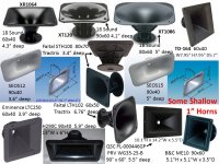

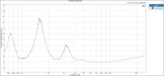
Often CD / waveguide combinations have 3 impedance peaks.
See the first plot below of a JBL D2 CD on a JBL PT H1010HF-1 waveguide. The second impedance peak is even larger than the first.
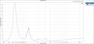
The second plot is the JBL 2425HS (screwed) CD on a smaller Baby Cheek JBL 4342.
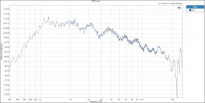
The third plot is the Frequency Response of the JBL 2425HS CD on a JBL 4342 waveguide.
Note that the impedance peaks can be largely reduced by placing a resistor equal to the impedance of the voice coil in parallel with the voice coil and placing a resistor equal to the parallel resistance of the Voice Coil plus the parallel resistor in series with the Voice Coil. This is a fixed L-Pad. The fixed L-Pad resistors will damp the original electro-mechanical-acoustic impedance / resonance peaks of the CD Waveguide combination.
Next trip to the lab I make and post some of the L-Pad damped impedance plots.
DSP does magic equalizing and correcting resonance.
Thanks DT
See the first plot below of a JBL D2 CD on a JBL PT H1010HF-1 waveguide. The second impedance peak is even larger than the first.
The second plot is the JBL 2425HS (screwed) CD on a smaller Baby Cheek JBL 4342.
The third plot is the Frequency Response of the JBL 2425HS CD on a JBL 4342 waveguide.
Note that the impedance peaks can be largely reduced by placing a resistor equal to the impedance of the voice coil in parallel with the voice coil and placing a resistor equal to the parallel resistance of the Voice Coil plus the parallel resistor in series with the Voice Coil. This is a fixed L-Pad. The fixed L-Pad resistors will damp the original electro-mechanical-acoustic impedance / resonance peaks of the CD Waveguide combination.
Next trip to the lab I make and post some of the L-Pad damped impedance plots.
DSP does magic equalizing and correcting resonance.
Thanks DT
Attachments
Last edited:
- Status
- Not open for further replies.