Got a beautiful old vintage SS amp to restore, but looks like someone has removed a few components. In particular, there is a SIP packaged dual JFET at the input (Q701). Manual calls for a M47F (C), whatever the hell that is...I certainly can't find any info on it besides the fact that the schematic shows it a dual N-Channel FET.
What I know about FET's could fit in a thimble. Any suggestions on what I could do to revive this thing? Wayyy to pretty to just have collect dust.
What I know about FET's could fit in a thimble. Any suggestions on what I could do to revive this thing? Wayyy to pretty to just have collect dust.
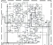
Attachments
If it matters (at this point...) the pinout of the 7-pin SIP is D-G-S-(NC)-S-G-D
Thanks for any input guys..
Thanks for any input guys..
You could try replacing it with some other dual JFET with an offset well below 14mV and an IDSS well above 1mA. (An offset of about 14mV or more will overdrive the DC bias loop and the gates will go in conduction when IDSS is less than about 1mA.)
I have been digging and digging. Apparently, Toshiba no longer has the datasheet for the 2K389. Hell, I can't even find out what package or pinout it uses, much less if it meets the parameters listed by MarcelvdG.
Anyone got a datasheet stored on a server somewhere? Or perhaps tell me if its parameters (and pinout) are suitable..??
Anyone got a datasheet stored on a server somewhere? Or perhaps tell me if its parameters (and pinout) are suitable..??

Apparently its offset is a bit too high, but you can increase the DC loop control range, for example by lowering R753 and increasing C711 by the same factor. With R753=47kohm and C711=1uF, the DC loop control range becomes about 30mV, which should be enough.
rickpt...thank you for the link!!
MarcelvdG, I see...you were referring to the differential G-S voltage...Duh! It wasn't obvious to me at first.
No reason why I can't tweak the servo loop...got all the components I need to do so. However, there are three Idss class ranges for the 2SK389 device...the 'GR' with a range of 2.6 to 6.5mA, the 'BL' with a range of 6 to 12mA, and the 'V', with a range of 10 to 20mA. Which one to hunt for?

Your assistance is most gracious MarcelvdG, and greatly appreciated. I got to find the parts and order them, but I believe this will do the trick.
There's more wrong that this though...although the fuse doesn't blow, the output of one channel is sitting at the Neg rail, so I've got some more troubleshooting to do before I claim victory. However, this input stage with the unknown FET was the big concern.
Thanks again...I'll post once I have parts and figure out where the fault is in the output stage.
By the way, there is one disadvantage of this circuit (both in its original and in its modified version) that I would like to mention. Because of the limited control range of the DC loop, the DC loop can easily be overdriven by deep subsonics in the input signal. In that case, a DC component might occur at the output. So if you're playing warped records and you have no subsonic filter anywhere in the signal path, be a bit careful with the volume knob.
Why not raise the value of the 120-ohm resistor, while dropping the value of the 100K one? I would think with proper selections that a range of a volt or two should be easy to do.
Raising the 120 ohm (R731) also decreases the closed-loop gain and may affect the stability, so I wouldn't touch that one.
You can decrease R753 (100kohm) a bit more than I originally suggested in order to increase the control range and reduce the risk of subsonics overdriving the circuit, but if you want to keep the low-frequency roll-off at the same frequency, you have to increase the product R761*C711 by the same factor.
If the op-amp Q721 has a negligible input bias current (for example, if it is a type with a JFET input), you can do that by increasing R761. If its input bias current is not negligible, increasing R761 will increase the output offset voltage, and it is then better to make C711 larger instead.
I just noticed R763. Its presence suggests that the op-amps have a non-negligible input bias current. Be careful not to increase R761 too much and always give R763 the same value as R761, so that the voltage drops due to the op-amp bias currents cancel.
One other thing, if you reduce R753 and put a DC voltage or deep subsonic at the input, the left op-amp will have to supply a larger output current than was originally intended and will therefore draw more current from the zener diodes. To minimise the risk of the zeners running out of current, I wouldn't reduce R753 below 5.6kohm or so. Values below 5.6kohm are not very useful anyway, because the amplifier then clips before the DC loop does.
In fact, you probably will have to use a much larger value than 5.6kohm for R753 because otherwise the increased C711 won't fit on the PCB.
Gonna dredge this back up since I'm almost ready to see if it'll actually work... 
The IC was replaced with a AD822 where bias currents are not a concern, but R761 & R763 are already 820K in the circuit as is...I see no real reason to change 'em
C711 was replaced with a 5.6µf metal polyester. It fit fine. R753 was changed from a 47K (it's was what in the circuit rather than a 100K) to a 12.1K. Hoping that will give a decent adjustment range.
Hopefully later this evening I can find the short in the output stages and see how this input works...
- Status
- Not open for further replies.
- Home
- Amplifiers
- Solid State
- Yikes!! FET Substitution? Could use some FET Guru's here...