There is no need to fit in size if the interface connector is the same !Danzup,
thanks for the answer.
But I do understand that bigger displays will (physically) not fit the PCB without modifying. Could you kindly confirm ?
Cheers,
Max
( no problems if the LCD is bigger if the connector fits well on pcb )
project nr.3 looks like just what I've been looking for!
I'm new to all this so I have some questions, anyone can help I would greatly appriciate it.
I plan on using it as a passive pre-amp for some chipamp.com gainclones, would it be suitable as is or would it need any modification?
If i did need to mod it do I just need to change the firmware on the atmega chip? I think I have a few atmega16's and a parallel port programmer from wii project so that would be handy 😀
Surface mount scares me a little as I've only ever done through hole but etching my own boards doesn't as I know I can get help with that. Is it better for me to make my own or are there through hole pcbs available? I'm happy to buy kits, I just don't trust my surface mount ability.
Thanks for sharing these designs with the community!
That project do not need modifying for gainclones.project nr.3 looks like just what I've been looking for!
I'm new to all this so I have some questions, anyone can help I would greatly appriciate it.
I plan on using it as a passive pre-amp for some chipamp.com gainclones, would it be suitable as is or would it need any modification?
If i did need to mod it do I just need to change the firmware on the atmega chip? I think I have a few atmega16's and a parallel port programmer from wii project so that would be handy 😀
Surface mount scares me a little as I've only ever done through hole but etching my own boards doesn't as I know I can get help with that. Is it better for me to make my own or are there through hole pcbs available? I'm happy to buy kits, I just don't trust my surface mount ability.
Thanks for sharing these designs with the community!
You can make your own through hole pcb as the schematics is there .
If you want some changes in firmware , based on my free time I will try to do the changes . The parallel port programmer is perfect !
Here some pcb with r-2r project made as through hole with some bigrelay and big pcb : Picasa Web Albums - suzuki-san - atenuator
I made this for a user that have a tube amplifier and that user want only the volume part . That is for your inspiration .
@ sparehead1 :
This Solder side and component side you ask.
Didiet
Thank you didiet7, that will help me a lot 🙂
@ sparehead1 :
This Solder side and component side you ask.
Didiet
Congratulation my friend !
That are good looking PCB !
@Danzup
I've built volume controller in January (page 9 of this thread). I had some problems because it was my first microcontroller project, but when I fixed all my mistakes, now it works perfectly, like Swiss clock.
I have only one problem. When I sit in my chair to listen to the music, I'm far away from preamp, so I can't see clearly volume setting, numbers are small or my eyes are weak, it doesn't matter. If I used LED display, I could have bigger numbers, but LCD is more "fancy".
Now I have an idea, but I don't know to realize it, so I need your help.
Instead of 2x16 LCD display, I want to use 4x20. All text will be displayed at upper two lines. Bottom two lines will be bar grafic display. Each 7x5 matrix will be one bar, so if I use 16 bars in each of two lines (it's more simple than to use all 20), I'll have 32 bars for 64 volume positions. Each odd or even volume position will add one bar more. I think it will improve this project and will be more attractive for other builders.
Is it possible to realize? Is it simple? Are there enough place in memory?
You must answer these questions. If you have time to write program, I'll be very happy and thankful.
This have been done in another personal project made by me and posted in the romanian forum as you see in the attached picture . So only need is my free time to add this for that project .@Danzup
I've built volume controller in January (page 9 of this thread). I had some problems because it was my first microcontroller project, but when I fixed all my mistakes, now it works perfectly, like Swiss clock.
I have only one problem. When I sit in my chair to listen to the music, I'm far away from preamp, so I can't see clearly volume setting, numbers are small or my eyes are weak, it doesn't matter. If I used LED display, I could have bigger numbers, but LCD is more "fancy".
Now I have an idea, but I don't know to realize it, so I need your help.
Instead of 2x16 LCD display, I want to use 4x20. All text will be displayed at upper two lines. Bottom two lines will be bar grafic display. Each 7x5 matrix will be one bar, so if I use 16 bars in each of two lines (it's more simple than to use all 20), I'll have 32 bars for 64 volume positions. Each odd or even volume position will add one bar more. I think it will improve this project and will be more attractive for other builders.
Is it possible to realize? Is it simple? Are there enough place in memory?
You must answer these questions. If you have time to write program, I'll be very happy and thankful.
Also a VFD work perfectly in place of LCD , as this is something i have successfully tried already .
Attachments
Delivery and Supply costs
I would like to purchase pcb's and pre programmed controller etc what are supply status and costs please (to UK)🙂
I would like to purchase pcb's and pre programmed controller etc what are supply status and costs please (to UK)🙂
@danzup
Yes, excellent, wonderfull, beautiful. I was sure you had idea, but never thought that you already made this. It is even better if it can be done with two lines LCD. Do not hurry, first finish your tone control firmware. I am patient, I can wait.
@both danzup and didiet78
VFD are really nice and cool, but hard to find in Serbia. I must stay with LCD.
Greetings to both of you.
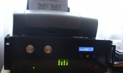
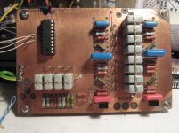
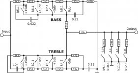
Hi all.
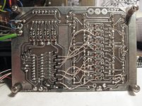
A month and a half ago I finished my tone control based on danzups firmware.
I made some changes for my needs. After some schematic and PCB additional changes it works properly🙂
Sweet sound with old-school soviet resistors is perfect😉
A month and a half ago I finished my tone control based on danzups firmware.
I made some changes for my needs. After some schematic and PCB additional changes it works properly🙂
Sweet sound with old-school soviet resistors is perfect😉
Attachments
I would like to purchase pcb's and pre programmed controller etc what are supply status and costs please (to UK)🙂
For those interested in DanZup VC we have opened a Group Buy http://www.diyaudio.com/forums/group-buys/158718-gb-r2r-audio-volume-input-selection-pcb.html
Regards,
Tibi
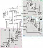
These are probably dumb questions but I'm a bit new to this. About the direct input. I dont really see its function but people seem to be happy that its there. Can someone explain it to me?
I cant see what Xrel0 is for. Is it a spare relay control?
I cant see what Xrel0 is for. Is it a spare relay control?
These are probably dumb questions but I'm a bit new to this. About the direct input. I dont really see its function but people seem to be happy that its there. Can someone explain it to me?
I cant see what Xrel0 is for. Is it a spare relay control?
That direct input is really an record output /line out of selected input source !
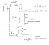
For Xrel0 the pictures is self explained .
Also with another firmware in case of use for tube amplifier Xrel0 command for 2 relay : first for main power/heater of tube and second for tube anodic +B voltage control (instead of controlling led ).
That direct input is really an record output /line out of selected input source !
For Xrel0 the pictures is self explained .
Also with another firmware in case of use for tube amplifier Xrel0 command for 2 relay : first for main power/heater of tube and second for tube anodic +B voltage control (instead of controlling led ).
ahhh. Thats great! That means its all ready to go for adding a sub 😀
I have made the firmware as requested .@danzup
Yes, excellent, wonderfull, beautiful. I was sure you had idea, but never thought that you already made this. It is even better if it can be done with two lines LCD.
Bin / hex atached .
Please program , use and tell if it is ok for you !
Attachments
Danzup, thank you very much. I expected to wait much longer. Tomorrow I'll try new firmware and post my impressions, but I'm sure you did it perfect.

- Home
- Source & Line
- Analog Line Level
- Yet another Volume controlers and source selections