The isolation for the transformer is quite simple....Just use a CSA or UL shrink tubing rated for 1500V over a 1000V rated litz wire, that was enought to pass the hipot test of 1500V. And best, temp rise of the toroid did not reach the max temp of 125 celcius for shrink. Look at ''sumi pac'' for real shrink tubing. For all one who ask for the core number, just to know that you can use nearly any core with 3f3 material, just to maybe change the primary to reach the point of minimal aidle current in the switching. The way we work here is that is faster to try than to simulate, so we take a core, only bobin the primary and find the number of turn who give the minimal idle current in the switch. At this point, because it was an unregulated switching power supply, it was easy to determine the ration for the secondary winding. If you whant to regulate it, just give 10% more than the desired output voltage with regulation and everything will be OK.
Just to let you know that I hate simulation software, they always give wrong result and take more time to debug a bad from the base design than directly experiment with real world parts...
Anyways, every one have is best way to do!
Bye
Fredos
www.d-amp.com
PS if anyone go to Montreal, go to the Parking night club, you will hear 48KW of pure sound...I have install 6X 8000HVI power amp for the main room yesterday, they have some Crown before and I can told you that Crown sound like s**t....No EQ have been done and now the sound was amazingly better (and louder too...)
Hi Fredos,
Do you never simulate?? What simulators have you tried.... dont' say EWB.
You have to realize there's a number of people like myself who enjoy the challenge this art provides, and don't have the resources to do with it what we'd like.
Parts can cost alot of money, many can be scavenged and the odd free samples are saviors. Making PCB's is not at all cheap, I haven't done one yet, and to this day have been unable to procure an oscilloscope 🙁
So for me, spice is all I've got. It does have certain advantages.
Regards,
Chris
PS: I'd like to know what "whole new way of doing class d" might be, even if it proved to not work. Drop me an email if you like. It is good to hear of creative thinking.
question to Fredos:
Hi, since you showed us the schematic of your 1200 model, could you explain us a bit more how the switching power supply work, and its limitations/characteristics.
thanks a lot
Pat Allen
Hi, since you showed us the schematic of your 1200 model, could you explain us a bit more how the switching power supply work, and its limitations/characteristics.
thanks a lot
Pat Allen
to fredos
Hi. In your schematic of D-Amp 1200 clock generator on CD4060 runs with 16Mhz crystal, but CD4060 works good only with 12MHz crystal if powered 15V. Any comments?
Hi. In your schematic of D-Amp 1200 clock generator on CD4060 runs with 16Mhz crystal, but CD4060 works good only with 12MHz crystal if powered 15V. Any comments?
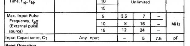
4060 work well at 15V if you dont use cap over the crystal! All my amplifier work with this clock generator and for about 6 years, no fault at all on this section! As you know to, 14060 and 4060 is not the same IC...What I use is the CD4060BE for Ti..Look at spec!
Fred
www.d-amp.com
Fred
www.d-amp.com
to fredos
Hi. I build amp from Your schematic D-Amp 1200. Supply +/- 85V.
With no input amp is very hot - 70Ñ. Where is trouble? Amplitude on gates of MosFET 8V aprox. Did R13 and R14 have different values?
Hi. I build amp from Your schematic D-Amp 1200. Supply +/- 85V.
With no input amp is very hot - 70Ñ. Where is trouble? Amplitude on gates of MosFET 8V aprox. Did R13 and R14 have different values?
Try to play with the value of the emiter resistor of the level shifter, you can also play with the gate resistor of the mosfet. If you have follow all parts, it should be work fine at power-up! How do you like the sound?
Fredos
www.d-amp.com
Fredos
www.d-amp.com
Dear Oldmaelstrom,
what type of protection - current limiter are you using?
Are you using the original PSU, or another one?
What are the optimal values of R26-C23 in your prototype?
Are the diodes after U12 working?
Thanks for the answer, best regards,
what type of protection - current limiter are you using?
Are you using the original PSU, or another one?
What are the optimal values of R26-C23 in your prototype?
Are the diodes after U12 working?
Thanks for the answer, best regards,
Hello Fredos,
I am intrerested abaout the final power stage but in an total N-fet
The mosfet witch I hawe is irfp260n; What kind of changes i need to make in your schematics to achive this? (replace p-fet with n-fet)
Any schematics with n-fet power stage is welcomed.
The pwm I intend to use is a copy of JBL car amplifier.
Sorry but I think I have give more than enought!
If nobody make experimentation, nothing will go forward!
I have work for more than 10 years in class d amplifier, I have made a lot of experimentation, so now it's your turn!
Just a cue, try the front stage with IR2110 mosfet driver...
Fredos
www.d-amp.com
If nobody make experimentation, nothing will go forward!
I have work for more than 10 years in class d amplifier, I have made a lot of experimentation, so now it's your turn!
Just a cue, try the front stage with IR2110 mosfet driver...
Fredos
www.d-amp.com
fredos ?
What do you think does it would be possible to simply inject some clocking signal into modulation stage, as I drawn in sch, and perhaps I do not need at all to remove trm. pot. of 5k, insted of this I just use a higher clock than is self oscillation freq. to be able to sync. those two.
So what is your oppinion ?
BTW. how is progressing your new class AD design, any pics etc. . . .
Best regards
Zeljko Kaiser
Attachments
The best way in this schematics to add reference clock is to remove positive input from ground and feed reference triangle wave to this point!
I have already start a news tread about my final project, look at the news DLS3000 tread! Product is finish and now in production.
I'm working too on a news design of phase modulated 2Kw heat sink less IGBT power amp...Look at this!
Fredos
www.d-amp.com
I have already start a news tread about my final project, look at the news DLS3000 tread! Product is finish and now in production.
I'm working too on a news design of phase modulated 2Kw heat sink less IGBT power amp...Look at this!
Fredos
www.d-amp.com
ok, but then I do not need startup circuitry cos. forced oscillation will at start skip first positive cycle, and as soon as negative cycle occurs bootstrap cap will be charged and system will continue to work normally, but don't I need anymore c33,34 and 5k trim. ?
btw. is it best to use quartz oscill. and then transforming square into triangle wave ?
thank's for fast response, have a nice day!
btw. is it best to use quartz oscill. and then transforming square into triangle wave ?
thank's for fast response, have a nice day!
Hello everybody again !
I was just wondering is it possible to occur a bad feedback response if I use +-25V insted of +-50V which was originally suggested by IR ? I asking this cos. this my version is still in testing phase and I've seccessfully added crystal controlled clock to lock freq. to 447.443kHz
(3.579545 MHz / 2^3)
Attachments
Nice work! Why heat sink on the IR2110? Just higger your gate resistor and reduce dead time to reduce dissipation in it! And important, run it at 10V, not higger!
Fredos
www.d-amp.com
Fredos
www.d-amp.com
they now works on 15V with 100ohm gate res. and 120nS of rising and falling delay is achieved at output of fets. . .
BTW. temp. on IR2110 is 50-60°C and 30-45°C on mosfet heatsink after all day working period . . . fo~450kHz
BTW. temp. on IR2110 is 50-60°C and 30-45°C on mosfet heatsink after all day working period . . . fo~450kHz
- Status
- Not open for further replies.
- Home
- Amplifiers
- Class D
- Yet another version of IR audio amp ??