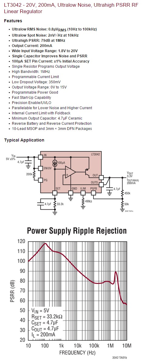
While I was amazed by ADM7150's performance, Linear tech released their best LDO ever - LT3042
The first sub-uv noise (0.8uv RMS @ 10Hz-100KHz) LDO on the market. What do you think?
The first sub-uv noise (0.8uv RMS @ 10Hz-100KHz) LDO on the market. What do you think?
Last edited:
They also just announced a couple of ultra low voltage switchers LTC3424 which will get you 3.3V or 5.0V from a single Lithium cell with very low noise.
Looks very impressive, but I can't find it at either Farnell or Mouser yet - may be too new. Anyone know of a UK supplier?
I would like to have seen the datasheet specify the 0.1Hz to 10Hz voltage noise. That can have oscillator application phase noise implications
Hi there, I'm new to this so please bear with me but I have a question about the LT3042.
Looking at the datasheet, they show a high current set-up of the LT3042 using an external PNP (D45VH10G) and with that it shows an Iout(max) of 1.5A rather than the standard 200mA of the LT3042.
My question is how do they get the max Iout of 1.5A?
Looking at the datasheet for the D45VH10G PNP it shows a max continuous collector current of 15A and a peak collector current of 20A. Am I missing something...?
Also, if I wanted to use the LT3042 to achieve a current draw of about 3.2A (or maybe slightly more to be safe) what would the best way to go about doing that?
I'm thinking of heating an 845 with a very clean dc power supply.
Many thanks,
Jeroen
take a look at the relationship between collector current and base current and between collector current and Vbe for transistors and then examine what's driving the base of the D45VH10G
-5V
I understand that both ADM7150 and LT3042 are positive regulators.
Where is the -ve regulators?
What is there for -5V with similar performance?
I understand that both ADM7150 and LT3042 are positive regulators.
Where is the -ve regulators?
What is there for -5V with similar performance?
What is the best option for caps at the output ? All those new LT regs are stable with ceramic ....but smd caps have some cracking piezzo noise : should we care about it for digital stuffs and swap the ceramics with other technology despite the good inductance of small X7R smd size ? bigger tantalum/polymer ? 2.5 mm pitch legs radial MKT ?
The LT3042 appears especially impressive for instrumentation. What I find disappointing is there's no negative-voltage mate for building a positive-ground-negative power supply.
The LT3042 appears especially impressive for instrumentation. What I find disappointing is there's no negative-voltage mate for building a positive-ground-negative power supply.
Not a problem if you use a power transformer with two separate floating secondaries (no center tap) and arrange the regulator outputs in a "totem pole" configuration.
Mike
Thanks or your reply, Mike. That is good, and most encapsulated transformers will satisfy that requirement. Something has me pondering, though.
According to the datasheet, the LT3042's PG, PGFB, ILIM and SET pins cannot be driven more than 0.3V below ground during normal operation, or a fault condition. On its own, this is fine, but I'm trying to envision how two LT3042 rectifiers could be arranged to provide a common return path for (+15)-0-(-15) output without these pins on the now-negative half being below ground? If you could provide a schematic drawing it would be excellent and a great help.
According to the datasheet, the LT3042's PG, PGFB, ILIM and SET pins cannot be driven more than 0.3V below ground during normal operation, or a fault condition. On its own, this is fine, but I'm trying to envision how two LT3042 rectifiers could be arranged to provide a common return path for (+15)-0-(-15) output without these pins on the now-negative half being below ground? If you could provide a schematic drawing it would be excellent and a great help.
Last edited:
Thanks or your reply, Mike. That is good, and most encapsulated transformers will satisfy that requirement. Something has me pondering, though.
According to the datasheet, the LT3042's PG, PGFB, ILIM and SET pins cannot be driven more than 0.3V below ground during normal operation, or a fault condition. On its own, this is fine, but I'm trying to envision how two LT3042 rectifiers could be arranged to provide a common return path for (+15)-0-(-15) output without these pins on the now-negative half being below ground? If you could provide a schematic drawing it would be excellent and a great help.
TI Tina doesn't have that part in it's library so I'm using a standard LM317 circuit for illustrative purposes, just substitute the LT3042 circuit, it will work the same. Notice the only common connection point is the negative side of the upper regulator and the positive side of the lower regulator. That junction is the only common connecting point, and provides the common "ground" for the supply.

Hope that helps.
Mike
Thank you Michael.
I appreciate the explanation and well-drawn image. It is what I had in mind, but the 0.3V clause unique to specific Linear devices, and having seen arrangements utilizing a single bridge rectifier, I initially had caused some concerns. I will report back once I have prototyped a pair. These may be suited to your latest preamp design.
I appreciate the explanation and well-drawn image. It is what I had in mind, but the 0.3V clause unique to specific Linear devices, and having seen arrangements utilizing a single bridge rectifier, I initially had caused some concerns. I will report back once I have prototyped a pair. These may be suited to your latest preamp design.
Thank you Michael.
I appreciate the explanation and well-drawn image. It is what I had in mind, but the 0.3V clause unique to specific Linear devices, and having seen arrangements utilizing a single bridge rectifier, I initially had caused some concerns. I will report back once I have prototyped a pair. These may be suited to your latest preamp design.
No problem. The main thing is, as long as you don't create a short circuit, the reverse voltage limitation shouldn't come into play. But if you need total peace of mind, a schottky rectifier with a forward voltage of 300 mV or less would fit the bill.
Mike
What is the best option for caps at the output ? All those new LT regs are stable with ceramic ....but smd caps have some cracking piezzo noise : should we care about it for digital stuffs and swap the ceramics with other technology despite the good inductance of small X7R smd size ? bigger tantalum/polymer ? 2.5 mm pitch legs radial MKT ?
Those caps are piezoceramic, but they're loaded into the very low impedance of the regulator, and driven by a low noise voltage, so they should be OK - external vibration will not be likely to corrupt the output, and they won't ring on their own with a linear regulator.
One issue to keep in mind is that many X7R caps lose capacitance with DC bias. Even a 50V cap can lose about half of its capacitance at 15-20V. So, they need to be oversized, and/or a 100V part is required to provide enough capacitance to stabilize the regulator. Still, these caps are really nice and small, and very inexpensive, so they're a lot easier to use than a film or tantalum.
Hi,
there's a model for the LT3042 in LTSpiceIV.
Beware though that at least the current limit pin behaves different to the datasheet.
Simulation results in lower resistor values than calculated after the Datasheet.
Also it doesn't limit current but reduces output voltage instead.
I hope to get information about the discrepancies tomorrow as it may also change the dimensioning of the PowerGood feature if one wants to use that for protection.
jauu
Calvin

- Home
- Amplifiers
- Power Supplies
- Yet another ultra low noise high PSRR LDO - LT3042