Are you sure?
I got the file already.
I tried the simulation. Seem look same result with mine. But the simulation does not show how the sound and how hot the parts.
I got the file already.
I tried the simulation. Seem look same result with mine. But the simulation does not show how the sound and how hot the parts.
Kartino,
If you have the power calculator module loaded you can see the dissipation in each part, hence if your 2N5401 is dissipating 5-watts you can be sure that it'll go up in smoke. The power calculator also allows you to do an automated efficiency calculation of each part, the output, etc.
As an added note if you add a .four <freq> V/I(Rx) as a spice directive you will get a listing of the THD in the .log file, below is an example for a 1KHz sine where I'm looking to find the THD of the voltage across R1 which is the output resistor.
SINE (0 1 1k)
.four 1KHz V(R1)
Best regards,
Sander Sassen
http://www.hardwareanalysis.com
MOER?
Guess what, it is about 4-posts up! You just need to download the LTspice simulator at http://www.linear.com to have a look at it, or is that too much trouble?
Best regards,
Sander Sassen
http://www.hardwareanalysis.com
Guess what, it is about 4-posts up! You just need to download the LTspice simulator at http://www.linear.com to have a look at it, or is that too much trouble?
Best regards,
Sander Sassen
http://www.hardwareanalysis.com
Re: UCD.zip
Hi Steve,
Have you tried the other side of the page?
I assure you the schematic is there, assuming you know it's an LTspice Netlist and simply are seeing nothing where the Netlist should be, you're possibly suffering from a software bug.
I zipped it in a semi recent version of WinRar, and I have seen WinRar break compatibility with older versions, simply would not extract properly, or at all. So I'd recommend you try a newer version of WinZip or WinRar and I'd imagine that will fix you right up.
I can't post the netlist code on its own it's too long, if the new program doesnt' help let me know and I"ll just email it, no problem.
/break
Hi kartino,
This is based off your sim. I was just using it to play in LTspice a little and mess around with snubbers and little things from time to time when I got the itch to do so. I can't even remember the exact changes. To your credit I recall the gate waveforms and output currents through them were very well refined as well. I've simulated this one with 100V rails and at 1 ohm load, still looked clean.
I've experienced gate waveforms which looked like those previously posted here in LTspice and the determining factor was the level of output current, at low output they looked fine. These drivers with the given values seem very robust wont' be easily loaded down, sounds like a good base point to anyone wanting to P2P it, that's why I decided to post it.
Of course I'm not going to say the first set of Mosfets are going to last more than a second, even with the power calc or smoke tests it isnt' an ideal sim so no matter what expect some smoke until final values can be determined. People may fear it for this but I'm sure we'll both agree it's well worth that little bit of effort, especially if it's the only way you can get to hear the kind of amp everyone has been talking about. Even my single ended version was stunning.
/break
Hi Sander,
Cool LTspice tips saves me some research, and will be very useful as I'm liking the reliability of it over the bugginess of Orcad.
Cheers to all,
Chris
MOER said:The UCD.ZIP file is a 4Kb file with a .ASC file which has nothing on it
Hi Steve,
Have you tried the other side of the page?
I assure you the schematic is there, assuming you know it's an LTspice Netlist and simply are seeing nothing where the Netlist should be, you're possibly suffering from a software bug.
I zipped it in a semi recent version of WinRar, and I have seen WinRar break compatibility with older versions, simply would not extract properly, or at all. So I'd recommend you try a newer version of WinZip or WinRar and I'd imagine that will fix you right up.
I can't post the netlist code on its own it's too long, if the new program doesnt' help let me know and I"ll just email it, no problem.
/break
Hi kartino,
This is based off your sim. I was just using it to play in LTspice a little and mess around with snubbers and little things from time to time when I got the itch to do so. I can't even remember the exact changes. To your credit I recall the gate waveforms and output currents through them were very well refined as well. I've simulated this one with 100V rails and at 1 ohm load, still looked clean.
I've experienced gate waveforms which looked like those previously posted here in LTspice and the determining factor was the level of output current, at low output they looked fine. These drivers with the given values seem very robust wont' be easily loaded down, sounds like a good base point to anyone wanting to P2P it, that's why I decided to post it.
Of course I'm not going to say the first set of Mosfets are going to last more than a second, even with the power calc or smoke tests it isnt' an ideal sim so no matter what expect some smoke until final values can be determined. People may fear it for this but I'm sure we'll both agree it's well worth that little bit of effort, especially if it's the only way you can get to hear the kind of amp everyone has been talking about. Even my single ended version was stunning.
/break
Hi Sander,
Cool LTspice tips saves me some research, and will be very useful as I'm liking the reliability of it over the bugginess of Orcad.
Cheers to all,
Chris
Hi, Chris and Sander,
Actually I always make sure that the components are not overloaded by see the value for each suspected components. For the 2N5401 max. load are : 100mA x 12V = 1.2W, no problem. Others are limited to 3mA.
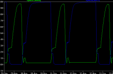
The problem that still I have is maybe caused by capacitive for each component and RC load at gate delay charging. It is looked that there small time that the gate have stated ON at the same time. Very small collision at the feet of graphic of hi and low gate at the simulation appeared. Does the problem came from there?
The UCD based is very-very good if correct component selected, But although very simple, but the ON and OFF time are influenced each other. I have idea to make faster charging by using higher power and speed BJT for gate charging. With higher power and speed we can make a faster active clamp too by using smaller value R for active clamp BJT without affecting the speed of charging. Any idea?
I have saw other design in this forum. Very good for gate charging form. But the problem is bad in balance. Chris please see other simulation that I have sent to you, and see the power (Vout*Iout). I have tried several modification and the conclusion, I back to optimise this UCD based.
Regards,
Kartino
Regards,
kartino
Actually I always make sure that the components are not overloaded by see the value for each suspected components. For the 2N5401 max. load are : 100mA x 12V = 1.2W, no problem. Others are limited to 3mA.
The problem that still I have is maybe caused by capacitive for each component and RC load at gate delay charging. It is looked that there small time that the gate have stated ON at the same time. Very small collision at the feet of graphic of hi and low gate at the simulation appeared. Does the problem came from there?
The UCD based is very-very good if correct component selected, But although very simple, but the ON and OFF time are influenced each other. I have idea to make faster charging by using higher power and speed BJT for gate charging. With higher power and speed we can make a faster active clamp too by using smaller value R for active clamp BJT without affecting the speed of charging. Any idea?
I have saw other design in this forum. Very good for gate charging form. But the problem is bad in balance. Chris please see other simulation that I have sent to you, and see the power (Vout*Iout). I have tried several modification and the conclusion, I back to optimise this UCD based.
Regards,
Kartino
Regards,
kartino
kartino said:Are you sure?
I got the file already.
I tried the simulation. Seem look same result with mine. But the simulation does not show how the sound and how hot the parts.
I just freshly simulated yours again and in doing so remembered why I started tweaking it, it's not the same at all.
kartino said:Hi, Chris and Sander,
Actually I always make sure that the components are not overloaded by see the value for each suspected components. For the 2N5401 max. load are : 100mA x 12V = 1.2W, no problem. Others are limited to 3mA.
The problem that still I have is maybe caused by capacitive for each component and RC load at gate delay charging. It is looked that there small time that the gate have stated ON at the same time. Very small collision at the feet of graphic of hi and low gate at the simulation appeared. Does the problem came from there?
The UCD based is very-very good if correct component selected, But although very simple, but the ON and OFF time are influenced each other. I have idea to make faster charging by using higher power and speed BJT for gate charging. With higher power and speed we can make a faster active clamp too by using smaller value R for active clamp BJT without affecting the speed of charging. Any idea?
I have saw other design in this forum. Very good for gate charging form. But the problem is bad in balance. Chris please see other simulation that I have sent to you, and see the power (Vout*Iout). I have tried several modification and the conclusion, I back to optimise this UCD based.
Regards,
Kartino
Regards,
kartino
I know the one you're talking about, I think it's an ambitious effort, I dont' think it would work well, as you say, such complication and for no reason that I can see.
There's a few things I want to point out, compare your schematic to mine, note what parts I changed and in what way. Those transistors in your comparator are only making it sloooow, same with those in the driver.
Proper part selection will make or break this.
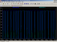
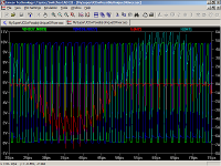
Here's your circuits gate waveforms, I'll post a real close up of mine next.
Both are at an input of 1 volt 20kHz and 4 ohm loads with the same 60V rails.
The current through mosfets looks fine, but that's because they're hardly turning on.
Attachments

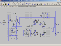
Oh, before anyone starts drafting a PCB based on that schematic, D18 and D19 should be removed, and a few other parts should be spec-ed up to handle the load. I just put the schematic through LTspice's Power Calculator and some parts are 200% over spec, which means they'll last a few seconds at best. Nevertheless Chris's design runs just fine in the simulator, well done Chris!
Best regards,
Sander Sassen
http://www.hardwareanalysis.com
Best regards,
Sander Sassen
http://www.hardwareanalysis.com
Removed? No they can stay. A proper selection of diode would be better for them though, I hadn't bothered with that for a proof of concept type of thing. If you don't want to use them, remove the paralleled ones too, they become useless.
200% overspec? Let's have that list please. I'm not so quick to trust the power calc.
Might want to also replace the ideal current source before you draft it up too 😉
Regards,
Chris
200% overspec? Let's have that list please. I'm not so quick to trust the power calc.
Might want to also replace the ideal current source before you draft it up too 😉
Regards,
Chris
SSassen said:Oh, before anyone starts drafting a PCB based on that schematic, D18 and D19 should be removed, and a few other parts should be spec-ed up to handle the load. I just put the schematic through LTspice's Power Calculator and some parts are 200% over spec, which means they'll last a few seconds at best. Nevertheless Chris's design runs just fine in the simulator, well done Chris!
Best regards,
Sander Sassen
http://www.hardwareanalysis.com
Hi,
Allow me to clarify. That's still just a tweaked schematic of someone else's which I messed with in order to show a more proper way of doing it. Those diodes should stay. It was simulated at 60 volts to give a more equal comparison with that of Kartino's sim. No one prototyping this ought to attempt that level of power as a first try, and when they get to scaling it up, if they can, they'll have the understanding required to make it happen.
So go ahead an draft a PCB, expect to tweak the values in a real world circuit, and don't be crazy with the level of power you expect from it. Also, some diodes could be better selected dependant upon their specific application, and I will leave it to you all to figure out which. Can't do it all for you, this is a learning experience, so enjoy it.
Regards,
Chris
Chris,
You have 1N914 diodes in series with the output MOSFET drains, these will only allow about 200mA to pass, hence your amp will not work but for very low power with these. D2 (also a 1N914) is another diode that needs beefing up, as it'll carry up to 4A peak and about 800mA nominal current and there are a few others as well. But I totally agree with your point of view on this, if anyone is interested in putting this to a PCB they need to take the time to properly understand the schematic, and fill in the blanks themselves, as I mentioned the concept is solid.
Best regards,
Sander Sassen
http://www.hardwareanalysis.com
SSassen said:Chris,
You have 1N914 diodes in series with the output MOSFET drains, these will only allow about 200mA to pass, hence your amp will not work but for very low power with these. D2 (also a 1N914) is another diode that needs beefing up, as it'll carry up to 4A peak and about 800mA nominal current and there are a few others as well. But I totally agree with your point of view on this, if anyone is interested in putting this to a PCB they need to take the time to properly understand the schematic, and fill in the blanks themselves, as I mentioned the concept is solid.
Best regards,
Sander Sassen
http://www.hardwareanalysis.com
Hi,
I guess I can see why you made that post now. Since I'd stressed the importance of proper part selection, I suppose it could have led someone to believe it was ready for etching. I don't usually go with the assumption people would think I'm that nice.
That wasn't at all my intention, and I thought that was made obvious with the small signal diodes in the output stage, you dont' even need powercalc for that to scream at you.
That doesn't mean it ought to be removed though, of course I put it there for a purpose, I trust you know what that is now?
The proper part selection I was talking about though had to do with the transistors, and you won't find one of those out of spec., but even if you did, there's more specs than just the few obvious ones. One example being slow rectifiers in the output stage have no place either, so I simply did not use slow ones. In spice a 1N914 will pass allll the current I like, dont' even have to edit the model.
Of course that lesson extends to everything, not even powercalc tells you about trace width or wire gauge or parasitic oscillations or EMI or... yyaaaaaaawn. Is it morning? What year is this?
So I was simply offering some tips with what I believe is true so that others who've some ambition and willingness to learn have some direction.
I'm certainly not in the business of providing finished schematics, or some kind of kit, or anything of that nature.
As far as I'm concerned that's still just Kartino's sim, with a few tweaks to help him along.
Cheers,
Chris
Hi Chris, thanks to assist me. I got a lot of experience in this schematic.
Hi, Sassen,
Actually for me, my problem is that no good enough parts in my country. I am very confident that the schematic is already correct
I already have non surface mounted PCB model and already built a pair of this amp. It works. I satisfied enough. My last problem is that the amp seem too slow at very litle volume. But it is in very litle volume. No problem, it is non commercial project.
I have long discussion with Chris, for all aspect of this amp. If you have ideas to make the amp better let us see.
BR/Kartino
Hey Kartino,
What kind of small signal transistors can you get there? Do you have any used equipment you'd be willing to harvest some from? It worked for me.
Also, what's the tolerance you've used on the resistors in the feedback network?
Regards,
Chris
What kind of small signal transistors can you get there? Do you have any used equipment you'd be willing to harvest some from? It worked for me.
Also, what's the tolerance you've used on the resistors in the feedback network?
Regards,
Chris
- Status
- Not open for further replies.
- Home
- Amplifiers
- Class D
- yet another UcD