Greetings to Bruno, classd4sure and kartino! 😉
When I saw this:
http://www.diyaudio.com/forums/showthread.php?s=&threadid=64763&perpage=40&pagenumber=2
i think: why not? Very inexpensive and easy to build, but.. Here are the questions:
1st: I don`t see C13,C14 (22pF) on pcb. Are they needed or not?
2nd: what switching frequencies at idle and at full power? How I can calculate it? Does it depend on hi- or low- freuqncy signal or 4/8/infinite Ohm load?
3: R7 & R10 (5 Ohm) seems to be quite small. I plan to use STP55NF06 (~1600pF input capacitance), so I change R7&R10 to 12 Ohm. Would it be enought or they must be 33-47 Ohm?
4: Q12 (BST40) - does they need additional cooling like radiator or
copper area on pcb? How many current draws from Q12 to output drivers in case of very slow and dumb MOSFETs (like IRFP150 - 3000+pF gate cap.) ?
5: If I change C18+C19 from 2uF to 1uF, would it increase switching
frequency twice? Any suggestion about type of these caps? One piece of generic MKP 1uF/250V (have a lot of them from dead ATX PSUs) would be anought for ~70W (25+25V supply rails) application?
6: How this amp behave in case of shorting output to ground or disconnected load?
Ah, and yes, does 1uF on inputs are enought for 20Hz-xxKHz responce?
PS here is direct links:
http://www.diyaudio.com/forums/attachment.php?s=&postid=732901&stamp=1127897020
http://www.diyaudio.com/forums/attachment.php?s=&postid=732904&stamp=1127897157
http://www.diyaudio.com/forums/attachment.php?s=&postid=732907&stamp=1127897427
http://www.diyaudio.com/forums/attachment.php?s=&postid=732908&stamp=1127897586
http://www.linear.com/company/software.jsp
tnx in advance
Kuzmenko said:Greetings to Bruno, classd4sure and kartino! 😉
When I saw this:
http://www.diyaudio.com/forums/showthread.php?s=&threadid=64763&perpage=40&pagenumber=2
i think: why not? Very inexpensive and easy to build, but.. Here are the questions:
1st: I don`t see C13,C14 (22pF) on pcb. Are they needed or not?
2nd: what switching frequencies at idle and at full power? How I can calculate it? Does it depend on hi- or low- freuqncy signal or 4/8/infinite Ohm load?
3: R7 & R10 (5 Ohm) seems to be quite small. I plan to use STP55NF06 (~1600pF input capacitance), so I change R7&R10 to 12 Ohm. Would it be enought or they must be 33-47 Ohm?
4: Q12 (BST40) - does they need additional cooling like radiator or
copper area on pcb? How many current draws from Q12 to output drivers in case of very slow and dumb MOSFETs (like IRFP150 - 3000+pF gate cap.) ?
5: If I change C18+C19 from 2uF to 1uF, would it increase switching
frequency twice? Any suggestion about type of these caps? One piece of generic MKP 1uF/250V (have a lot of them from dead ATX PSUs) would be anought for ~70W (25+25V supply rails) application?
6: How this amp behave in case of shorting output to ground or disconnected load?
Ah, and yes, does 1uF on inputs are enought for 20Hz-xxKHz responce?
PS here is direct links:
http://www.diyaudio.com/forums/attachment.php?s=&postid=732901&stamp=1127897020
http://www.diyaudio.com/forums/attachment.php?s=&postid=732904&stamp=1127897157
http://www.diyaudio.com/forums/attachment.php?s=&postid=732907&stamp=1127897427
http://www.diyaudio.com/forums/attachment.php?s=&postid=732908&stamp=1127897586
http://www.linear.com/company/software.jsp
tnx in advance
1. It'll work without them, try it with them. There's alot more than that that didnt' make it into this PCB.
2. The frequency varies but not by a large degree, an idle frequency around 400kHz should suffice to keep it above 350khz at all times.
3. Experimentation will best determine those values, and several spare sets of mosfets will help. Don't be shy to increase them if needed. The bias values of the turn on/off transistors may also be experimented with, try not to load the drivers down too much, but dont' drive them too hard.
4. They really only pass enough current to keep the transistor from saturating so they don't get worked too hard.
5. It would increase frequency and also prevent it from dropping for a lower impedance load. 2uF seems too big.
6. Shorting the output wouldnt' be a smart idea as there's no active current limiting protection circuitry. Disconnecting the load won't hurt it at all, I've done it hundreds of times, the post filter feedback keeps the filter Q under control.
I'd increase C2 to 100uF at least, and add another ~50k resistor from the output to ground or the negative rail to ensure the bootstrap cap always has a charge path.
I never used input coupling caps. I'd get familiar with this on the simulator first 🙂
Good luck, it's worth the effort.
Chris
Pierre said:Sorry, but I can't find the schematics, where are they?
Thanks!
The second last link in the first post contains Kartino's LTspice sim.
Here's mine:
http://www.diyaudio.com/forums/attachment.php?s=&postid=619527&stamp=1113471320
From:
http://www.diyaudio.com/forums/showthread.php?threadid=55385
Regards,
Chris
Hi,
For input cap, you can increase to pass enough the low frequency. I increase the cap to 10uF.
Please also check that the mosfet at the schematic was just because the available at LTSpice. You shall choose the prefered mosfet such as IRF540. And also the gate resistor shall at least 10ohm. If your mosfet get warmer use bigger value.
Even looked so simple, the circuit works on high frequency. Therefore the bias for the BJT for the gate mosfet are very sensitive. Use value not so far from the schematic. I already blown dozen of mosfet to get the real value.
BTW, I still have problem with this circuit. The sound quality degraded at very low input. It is the dilema, when I fix the problem I get hoter mosfet at high volume. But the problem only occur at very-very low, but the problem never happen at linear circuit. The good news is at the normal volume the sound is like you have expensive amp.
I have updated the PCB, but I will not on the desk until next week.
br/tn
kartino said:Hi,
BTW, I still have problem with this circuit. The sound quality degraded at very low input. It is the dilema, when I fix the problem I get hoter mosfet at high volume. But the problem only occur at very-very low, but the problem never happen at linear circuit. The good news is at the normal volume the sound is like you have expensive amp.
br/tn
What did you perceive the problem to be and how did you attempt to fix it?
Regards,
Chris
In a sense class D is a switching class B amplifier, so I can't understand how you will ever not have to deal with the problem of crossover distortion. For some reason though some designs have no problems with this which is great. But as soon as you said what you did, my mind went right to class B crossover distortions which are at their greatest at low output levels. So the question is, how do some class D designs solve this problem, and how can it be implimented into this cicuit?
How does this circuit contol dead time?
Do not self oscillating class D amps self correct?
It almost sounds like the circuit needs a small adjustment to be more sensitive to this at lower wattage levels?
Terry🙂
P.S. "Jaya Raya"
How does this circuit contol dead time?
Do not self oscillating class D amps self correct?
It almost sounds like the circuit needs a small adjustment to be more sensitive to this at lower wattage levels?
Terry🙂
P.S. "Jaya Raya"
Tripath may corrected the distortion by gigantic loop gain of delta-sigma converter.
Genral self oscillating class D couldn't fully eliminate cross-over distortion, as experimented with a crappy output stage.
Genral self oscillating class D couldn't fully eliminate cross-over distortion, as experimented with a crappy output stage.
So the question is, how do some class D designs solve this problem, and how can it be implimented into this cicuit?
How does this circuit contol dead time?
Do not self oscillating class D amps self correct?
[/B]
Kuzmenko said:I mean- I don`t like BOTH of half- wave
Is there are some troubles?
Kenshin said:Tripath may corrected the distortion by gigantic loop gain of delta-sigma converter.
Genral self oscillating class D couldn't fully eliminate cross-over distortion, as experimented with a crappy output stage.
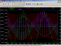
That's about as good as I"ve gotten them to work in LTspice as well. It can be made to look very good at low power, but crank up the input and that's exactly what happens.
This same behavior isn't observed to such an extent on Pspice so I'd imagine it has to do with the simulator. The question being which is truer to life?
I'm not saying that wouldn't occure in the actual circuit but perhaps not to such an extent.
Regards,
Chris
Hi,
I believe the cause of the cross over distortion is the inductor current and less than ideal switch. The mosfets and their body diodes do have some voltage drop across them. So we either require smarter circuitry and/or better components.
Regards,
Chris
I believe the cause of the cross over distortion is the inductor current and less than ideal switch. The mosfets and their body diodes do have some voltage drop across them. So we either require smarter circuitry and/or better components.
Regards,
Chris
Hi, nice to see you all again,
Actually when the dead time too long the sound quality degraded at very low volume. But at normal listening are no problem. When the dead time too fast the problem fixed, but at high volume the fets getting hot, seem that the current flows crossing the bots fets.
I can not fix the problem, except just accept the minor things. For me it is not easy to control on-off the mosfet using BJT. Are the BJT too slow?
But for your experience or if you just want to listen the sound is no problem. But if you want to build are commercial quality or you want to compare to SS amp, the circuit shall be refine, maybe using mosfet driver IC or small mosfet for driver.
br/tn
kartino said:Hi, nice to see you all again,
Actually when the dead time too long the sound quality degraded at very low volume. But at normal listening are no problem. When the dead time too fast the problem fixed, but at high volume the fets getting hot, seem that the current flows crossing the bots fets.
I can not fix the problem, except just accept the minor things. For me it is not easy to control on-off the mosfet using BJT. Are the BJT too slow?
But for your experience or if you just want to listen the sound is no problem. But if you want to build are commercial quality or you want to compare to SS amp, the circuit shall be refine, maybe using mosfet driver IC or small mosfet for driver.
br/tn
Dead time really should be kept minimal. Really there is no dead time other than the natural delays so you have to pay careful attention to turn on/off delays and such. Have the turn on at least two times slower than turn off and try to have the gate signals intersect right at the threshold.
I think it's because the deadtime are added to propgation delay when output current > free whirling current; but it's not added when output current < free whirling current.
If not loaded, there's no crossover distortion observed.
If not loaded, there's no crossover distortion observed.
classd4sure said:Hi,
I believe the cause of the cross over distortion is the inductor current and less than ideal switch. The mosfets and their body diodes do have some voltage drop across them. So we either require smarter circuitry and/or better components.
Regards,
Chris
Kenshin said:I think it's because the deadtime are added to propgation delay when output current > free whirling current; but it's not added when output current < free whirling current.
If not loaded, there's no crossover distortion observed.
Hi,
It does add to the delay however the delay is a part of the feedback loop and so this shouldn't account for much distortion. Were there no voltage drop across the switches, it would still make a smooth transition.
I have seen papers on class d distortion that account for it by adding an offset bias much like class B does to minimise this effect.
Regards,
Chris
Kuzmenko said:I mean- I don`t like BOTH of half- wave
Is there are some troubles?
Hi,
Here's one I've been playing with, simulates extremely well.
Regards,
Chris
Attachments
- Status
- Not open for further replies.
- Home
- Amplifiers
- Class D
- yet another UcD