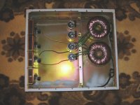
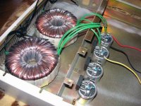
200W trafos, 10mF capacitors, non-inverting configuration dual stereo.
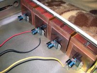
Intended for bi-amping, hence the small heatsinks.
The case is actually bottom-up in the pictures, it's an old pc case from some ancient cluster or smth (no openings in the front panel)
Intended for bi-amping, hence the small heatsinks.
The case is actually bottom-up in the pictures, it's an old pc case from some ancient cluster or smth (no openings in the front panel)
Attachments
I like it. I've been planning on using some Copper computer heatsinks myself.. Those look like they're for a Pentium Pro or maybe a socket A chip?
Nuuk: yeah, neat and very compact
motherone: yep, these are Socket A heatsinks. Got them from a local supplier for about 3$ each and they even had fans! Though they were very noisy and as these heatsinks proved to be quite effective up to about 50W output power, I decided to get rid of fans altogether.
motherone: yep, these are Socket A heatsinks. Got them from a local supplier for about 3$ each and they even had fans! Though they were very noisy and as these heatsinks proved to be quite effective up to about 50W output power, I decided to get rid of fans altogether.
I like the zero tolerance of pcb/strip board.😉
This must limit the choice of components based on physical size. Could you give a rundown of the amp components for those of us who can't yet tell a capacitor from a resistor.
This must limit the choice of components based on physical size. Could you give a rundown of the amp components for those of us who can't yet tell a capacitor from a resistor.
wxn said:Nuuk: yeah, neat and very compact
motherone: yep, these are Socket A heatsinks. Got them from a local supplier for about 3$ each and they even had fans! Though they were very noisy and as these heatsinks proved to be quite effective up to about 50W output power, I decided to get rid of fans altogether.
Lucky you! I've been looking for copper socket-A coolers, but haven't been able to locate a deal like that. Most of the suppliers out there will charge you more for the shipping than the heatsinks cost!
You'd think there'd be some good places to get stuff like that here in Seattle, but I must always miss the sales where they clear them out 😀
One thing that comes to mind is have you thought about using thermal epoxy to mount the chips to the heatsinks? It'd be a nice, no-screw method to do it. Might be worth it once you verify that the amp works, and assuming all the heatsinks are isolated from each other and the chassis.
jimbo1968 said:I like the zero tolerance of pcb/strip board.😉
This must limit the choice of components based on physical size. Could you give a rundown of the amp components for those of us who can't yet tell a capacitor from a resistor.
Sure, I'll post the schematic soon. But there's nothing special, usual NIGC.
motherone said:One thing that comes to mind is have you thought about using thermal epoxy to mount the chips to the heatsinks? It'd be a nice, no-screw method to do it. Might be worth it once you verify that the amp works, and assuming all the heatsinks are isolated from each other and the chassis.
Yes, I have thought about that. I have even experimented with simple epoxy glue and an insulator (paper towel - about 20microns which was too thick, only appropriate for 30W or so. Sliced mica should do better but I haven't done any experiments yet).
Anyway I will use screws for this project as these heatsinks are a bit small (+-35V supply) and a good physical contact with the case could provide additional heasinking which is important as I'm not planning to put any fans there.
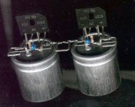
Attached a closeup 🙂
Attachments
Not sure about the "comp" part but yes, those are carbon 5% resistors. Though picked by hand to about 1% accuracy.
Sorry guys, can't help here. I just go to the nearest shop and buy some resistors. And they are cheap ones, not some audiophile type 😉
- Status
- Not open for further replies.
- Home
- Amplifiers
- Chip Amps
- Yet another pseudo GC in progress


